POOL AND SPA/HOT TUB HEATERS H150FD, H200FD, H250FD, H300FD, H350FD & H400FD MODELS SERVICE & INSTALLATION MANUAL FOR YOUR SAFETY WARNING: If the information in these instructions is not followed exactly, a fire or explosion may result causing property damage, injury, or death. - Do not store or use gasoline or other flammable vapors or liquids in the vicinity of this or any other appliance. WHAT TO DO IF YOU SMELL GAS: • • Do not try to light any appliance.
Contents Section I General information............................ 7 Introduction . ................................................... 7 Warranty ......................................................... 7 Maintaining proper water chemistry ............... 7 Section II Installation ......................................... 9 Equipment inspection ..................................... 9 Important notice . ............................................ 9 Conformance with codes ................................
safety information Basic safety precautions should always be followed, including the following: Failure to follow instructions can cause severe injury and/or death. This is the safety-alert symbol. When you see this symbol on your equipment or in this manual, look for one of the following signal words and be alert to the potential for personal injury. WARNING warns about hazards that could cause serious personal injury, death or major property damage and if ignored presents a potential hazard.
Notes to the electrician: Use a solid copper conductor, size 8 or larger. Run a continuous wire from external bonding lug to reinforcing rod or mesh. Connect a No. 8 AWG solid copper bonding wire to the grounding lug provided on the heater and to all metal parts of swimming pool or spa, and to all electrical equipment, metal piping (except gas piping), and conduit within 5 ft. (1.5 m) of inside walls of swimming pool or spa.
WARNING – Failure to remove pressure test plugs and/or plugs used in winterization of the pool/spa from the suction outlets can result in an increase potential for suction entrapment as described above. WARNING – Failure to keep suction outlet components clear of debris, such as leaves, dirt, hair, paper and other material can result in an increase potential for suction entrapment as described above.
WARNING – The following “Safety Rules for Hot Tubs” recommended by the U.S. Consumer Product Safety Commission should be observed when using the spa. 1. Spa or hot tub water temperatures should never exceed 104°F [40°C]. A temperature of 100°F [38°C] is considered safe for a healthy adult. Special caution is suggested for young children. Prolonged immersion in hot water can induce hyperthermia. 2.
Section I. General Information 7 Introduction: This manual contains instructions for installation, operation, maintenance, troubleshooting, and parts lists for the safe use of the swimming pool/spa/hot tub heaters. Hayward strongly recommends that the installer read the manual before installing the swimming pool/spa/hot tub heater. If after reviewing the manual any questions remain unanswered, contact the factory or local representative.
2. POOL/SPA WATER CHEMISTRY The chemistry balance and mineral content of swimming pool water changes daily due to the addition of pool and sanitizing chemicals, bather loads, rain, runoff and the amount of sun - to name a few. Improper chemistry balance and mineral content can cause scaling and deposits to form on pool walls, in the filtration system, in the heat exchanger tubes and additionally can promote corrosive action to all metals in the water path.
Section II. Installation 9 Equipment inspection: On receipt of the heater, inspect the heater carton(s) for damage. If any carton(s) is damaged, note it when signing for it. Remove the heater from the carton(s) inspect it and advise the carrier of any damages at once. Important notice: The installation instructions are intended for the use of a qualified technician, specifically trained and experienced in the installation of this type of heating equipment.
FDXLHAK1930 (sold separately) may be necessary. 3. If installing indoors, select the appropriate high-altitude indoor vent pressure switch from the indoor adapter kit or from the FDXLVPS1931 kit. Each switch has a label which identifies which model(s) and altitude range(s) it is designed for. 4. If connected, turn pump, main gas valve, and heater power off. 5. Remove heater front access door. 6.
Uncrating the heater: Figure 1 To remove the shipping carton from the heater: 1. Remove the corrugated carton from the heater. The carton, top pad, bottom pad, and the four corner posts can be recycled. 2. There are three (3) screws total used to secure the heater to the wood pallet. All three must be removed to separate the heater from the pallet. One (1) is located in the lower rear of the heater as shown in Figure 1. 3.
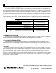
6. Do not install within 24” of any outdoor Table 1 HVAC equipment. Outdoor Installation Clearances 7. Do not install where water may run-off a Heater Panel Required Clearance roof into the heater. A gutter may be needed Top Unobstructed to protect the heater. Front 24 inches 8. Any enclosure around the heater must Back 6 inches provide a combustion air vent commencing Water Connection Side 12 inches within 12 inches of the bottom of the enclosure.
INDOOR INSTALLATION AND VENTING Positive and Negative Pressure Venting Systems The heater is designed such that it may be vented using either a negative-pressure or a positive-pressure venting system. The appropriate system of venting for a particular site will depend on many factors such as vent termination needs (horizontal/vertical), and the cost of venting system. Table 2 lists the indoor venting kits available and the limitations of each system.
(A) All Air Supply From Inside the Building: The confined space shall be provided with 2 permanent openings communicating directly with an additional room(s) of sufficient volume so that the combined volume of all spaces meets the criteria for an unconfined space (a space whose volume is not less than 50 cubic feet per 1,000 btu/hr). The total input of all gas utilization equipment installed in the combined space shall be considered in making the determination.
VERTICAL VENTING – NEGATIVE PRESSURE Vent Sizing Size the vent pipe according to the venting tables in the National Fuel Gas Code (ANSI Z223.1/NFPA 54) for a Category I gas appliance using single-wall or double-wall (Type B) gas vent. Vent pipe diameter should not be less than the size of the vent pipe adapter on the heater (see Table 5). The maximum vent height cannot exceed 50 ft. The total lateral (horizontal) length cannot exceed 1/2 of the total vent height.
HORIZONTAL OR VERTICAL VENTING – POSITIVE PRESSURE Vent Sizing Vent pipe diameter must match the vent pipe diameter on the heater (see Table 7). The vent pipe must be Heatfab single or double-wall stainless steel sealed vent as listed in Table 7. Double-wall vent must be used in non-conditioned spaces. The maximum total length of vent pipe, and number of 90-degree elbows cannot exceed the limits specified in Table 8.
Table 7 Vent Pipe & Terminal Specifications for Positive-Pressure Indoor Vent Kits Kit Part Number Heater Model Nominal Vent Pipe Diameter Vent Type Single-Wall UHXPOSHZ11501 UHXPOSHZ12001 H150FD H200FD 6 inch Horizontal Vent Terminal Vertical Vent Terminal Heatfab Saf-T Vent EZ Seal P/N 960x * Heatfab P/N 9614TERM (elbow terminal) and 5691CI (wall penetration) Heatfab P/N 5600CI Heatfab SafT Vent CI Plus P/N CCA06Lxx ** Heatfab P/N 9614TERM (elbow terminal), CCK06FC (collar), CCA06ADSV (c
VENT KIT INSTALLATION PROCEDURE (positive and negative-pressure venting) 1. If connected, turn pump, main gas valve, and heater power off. 2. Locate the heater as close as practical to the gas vent exit. 3. Remove the countersunk phillips-head screws and remove the flue cover panel on top of the heater and discard. Save the countersunk screws as they will be re-used later. 4. Remove the screws that fasten the heat barrier to the heater. Remove the heat barrier and discard. See Figure 4. 5.
Vent Adapter Heat Barrier Rain Guard FIGURE 5 FIGURE 4 Flue Cover FIGURE 6 FIGURE 7 Vent Pressure Switch Blower Air Inlet Plate Blower Pressure Tap FIGURE 8 Vent Pressure Switch Tubing USE ONLY HAYWARD GENUINE REPLACEMENT PARTS Pomona, CA Clemmons, NC Nashville, TN Tel: 908-351-5400 www.haywardpool.
Reversible water connections: This heater is designed so that it can be installed with the water connections located on either the right or left side. Heaters are factory-shipped with right-side water connections. To move the connections to the left side follow the instructions below and see Figure 15. A trained service technician should perform these steps before the heater is installed. Figure 14: Screw Locations Figure 14 1.
Top Flue Cover Louvered Exhaust Panel Rain Shield Assembly Heat Exchanger Assembly Temperature Limit Switch Water Pressure Switch Water Temperature Sensor Upper Plastic Heater Side Panel Ignition Control Board Upper Plastic Heater Side Panel Front Access Panel Figure 15 USE ONLY HAYWARD GENUINE REPLACEMENT PARTS Pomona, CA Clemmons, NC Nashville, TN Tel: 908-351-5400 www.haywardpool.
Gas Supply and Piping : Refer to the charts below in Figure 16 for gas pipe sizing for low pressure natural gas, low pressue propane gas, two-stage natural gas and twostage propane gas systems. Figure 16 : GAS PIPE SIZE Follow local gas codes for proper gas line material selection (copper, iron, plastic, etc.) LOW PRESSURE NATURAL GAS PIPE SIZING: (Based upon an inlet gas pressure of 0.5 psig or less at a pressure drop of 0.
It is VERY IMPORTANT when installing a propane heater on a 2-stage regulation system to follow the gas line sizing chart below without exception.
gas supply installation: The heater is shipped from the factory with the gas connection located on the left-hand side of the heater cabinet. Insert the pipe to the gas valve through the grommet in the cabinet side (see Figure 18.) A union should be installed outside the heater cabinet for easy removal of the gas manifold assembly during service. A CSA certified main gas shutoff valve must be installed outside the cabinet and within 6 feet of the heater. This valve must have an I.D.
ATTENTION: Whenever a high-pressure double regulation system is utilized for propane gas, consult a propane expert for accurate pipe and pressure sizing. Make sure that 1st and 2nd stage regulators are large enough to handle the BTUH input listed for the heater(s) being used. Hayward will not be responsible for heaters that soot up due to improper gas line or propane tank sizing resulting in improper gas volume.
If the normal pump and filter system flow rate exceeds 125 gpm then a manual bypass valve must be installed as shown in Figure 21. Damage caused by flow rates outside this range will void the manufacturer’s warranty. The installation is as follows: 1. Install a flow meter on the outlet line of the heater. 2. Adjust the manual bypass valve until the flow rate is within the flow rate range specified for the heater. 3.
Figure 23: Multiple heater system Figure 22: Typical plumbing to pool Installation above pool/spa surface: If the heater is installed less than three (3) feet above the surface of the pool/spa water, install eyeball fittings or directional flow fittings on the end of the return water line to the pool/spa to create adequate back pressure at the heater to operate the pressure safety switch when the filter pump is running.
Pressure relief valve: It may be necessary to install a pressure relief valve to conform with local building codes. A ¾” pressure relief valve with a discharge capacity greater than or equal to the BTUH input of the heater and a pressure relief rating less that the heater working pressure is recommended. See the heater rating plate located on the base pan inside the front access panel for the input rating and working pressure.
Electrical connections: The heater is equipped with a hot surface ignition control system that automatically lights the burners. An external power supply is required to power the control system. The heater is shipped from the factory wired for use with 240VAC, 60 Hz field power supply. To convert the heater to 120VAC, 60 Hz operation remove the 240VAC voltage selector jumper from the ignition control board and replace it with the 120VAC jumper.
Figure 28: Wiring connection diagram.
Remote control connection: The heater is equipped for conFigure 29 nection to an external 2-wire remote thermostat or a 3-wire remote switch. A 2-wire thermostat has its own temperature sensor for regulating water temperature. A 3- wire remote switch allows the “POOL” or “SPA” models to be remotely selected. Connect remote wiring to the terminal block located in the lower compartment inside the junction box (see Figures 27 and 29). The heater has 2 junction boxes (one on each side of the heater).
Figure 30: Lighting & Operating instructions label
Section III. Installer Check-out and Start-up General: 33 Some of the following procedures will require the heater to be operating. Full lighting and shutdown instructions are included on the lighting and operating label affixed to the inside of the front access panel. The heater automatically lights in response to a call for heat, and automatically shuts down when that call for heat is satisfied. Water must be flowing through the heater during operation.
32 34 If gas pressure is inadequate, check for undersize piping between the gas meter and the heater or for a low-capacity gas meter. Gas pressure test procedure: 1. Obtain the necessary equipment: a. Manometer to read pressure in inches of water column b. 1/8” pipe nipple (1/8” thread x 1” long) c. 3/16” hex wrench d. Flat screwdriver WARNING: EXPLOSIVE HAZARD. of an open flame to check for gas 2. Remove the 1/8” plug from The the gasuse valve. 3. Install the 1/8” pipe nipple into the gas valve.
9. Remove the 1/8” pipe nipple and replace the 1/8” pipe plug. If proper pressure cannot be achieved by adjusting the gas valve regulator, the installer must contact the gas supplier and request that the inlet pressure to the heater be set to within the gas pressure range shown in Figure 33. Figure 33: Correct gas pressures FDN FDP Pressure, in. w.c. Natural Propane Fuel 1.8” - 2.0” w.c. 6.8” - 7.0” w.c. Manifold 4.5” w.c. 9.0” w.c. Inlet, minimum 10.5” w.c. 13.0” w.c.
Temperature control operation: The heater is equipped with a Temperature Control for controlling the pool and spa water temperatures. Individual pool and spa set points can be entered using the keypad (see Figure 27 for the location of the keypad and Figure 35 for a view of the keypad). The control displays the pool or spa water temperature and, if needed, diagnostic information.
6. When the thermostat is satisfied and the call for heat ends the control immediately de-energizes the gas valve. Flame is extinguished. 7. The control operates the blower during a 30-second post-purge period. Failure to light – retry: If the first ignition attempt fails during a normal heating cycle the control will make two (2) additional ignition attempts: 1. The control de-energizes the gas valve after the 4-second ignition trial ends. 2.
3. It is normal for the heater to display up to a 5-second delay when the keypad is used to reset the control to clear an error code. 4. The control will accept a mode change during lockout after 5 seconds. The control will continue to display the error code and remain in lockout until it is reset. At reset the control will go to the last saved mode. Automatic reset time: The heater will automatically reset when an error condition is corrected and resume operation as detailed in the table below.
ATTENTION: A heater damaged by freezing is not covered under the Haywawrd warranty. Removing the drain plug: 1. 2. 3. 4. 5. 6. 7. 8. 9. This procedure is for above-pool installations only. See Figure 36 for the location of the drain valve on the header. Set the keypad to “STANDBY”. Turn the electricity “OFF” at the circuit breaker. Turn the heater gas valve “OFF” using the knob on the valve. Turn the heater’s gas supply “OFF” at the main shut-off valve outside the heater cabinet.
Section IV. Qualified Technician – Maintenance & Servicing General: ATTENTION: Only qualified service technicians, with appropriate test equipment, should be allowed to service the heater. Bear in mind that all of the components that comprise the system have an effect on heater operation.
External heat exchanger inspection and cleaning: Remove the heater top and inspect the external surfaces of the heat exchanger for soot accumulation. If soot has accumulated it must be removed by following the recommended procedure. 1. Turn pump, main gas valve, and heater power “OFF”. 2. Remove the trim panels at each end of the heater. Each is secured with (4) screws. 3. Remove upper end caps on both ends of the heater.
Burner inspection and cleaning: With the heater “ON”, remove the front access panel and make a visual inspection of the main burners through the sight glass (see Figure 31.) The main burner flames should be about ½” to 2” in height and should not “lift” off the burner ports (see Figure 39). A normal flame is blue, without yellow tips. Yellow tips or a totally yellow or “lazy” flame may be an indication of a fuel-rich mixture due to restricted air supply.
Burner installation: Refer to Figure 40 as needed. 1. Reverse the above procedure to install the burners. 2. Turn the gas supply “ON”. Use a soapy water solution to check for leaks. 3. Bubbles forming indicate a leak. 4. To start the heater, follow the instructions on the label inside the front access panel (see Figure 30).
Igniter: Refer to Figures 31 and 37. To remove the igniter: 1. Turn pump, gas supply, and heater power “OFF”. 2. Remove the front access panel. It is secured with (4) screws. 3. Remove the control box cover. It is secured with (2) screws. 4. Disconnect the igniter wires from the ignition control board. 5. Pull the igniter wires out of the control box through the opening in the bottom. 6. Remove the screws from the igniter access panel.
Gas conversion: The factory-installed gas train, where appropriate, may be changed from natural gas to propane or from propane to natural gas, using the appropriate conversion kits available from the factory. Gas conversions are to be performed only by a qualified service agency. Detailed instructions are included with each kit. ATTENTION: Conversion kits are not available in Canada. Conversions must be performed by the conversion station at Hayward Pool Products Canada, Inc.
Ignition control board: The ignition control board features an integral thermostat and uses special technology and software for optimum performance of a silicon nitride igniter element. See Figure 42. To remove the ignition control board: Figure 43: Display board and keypad: 1. Turn pump, gas supply, and heater power “OFF”. 2. Remove the front access panel. It is secured with (4) screws. Remove the control box cover. It is secured with (2) screws. 3.
To remove the blower vacuum switch: 1. Turn pump, gas supply, and heater power “OFF”. 2. Remove the front access panel. It is secured with (4) screws 3. Remove the wires from the pressure switch. 4. Pull the tubing from the hose barb on the switch. 5. Remove the (2) screws that secure the pressure switch to the control panel. 6. Replace the switch. Reverse steps 1 – 6 to complete the procedure.
Thermistor: Figure 47: Thermistor The thermistor monitors the return water temperature. See Figure 47. To replace the thermistor: 1. Turn pump, gas supply, and heater power “OFF”. 2. Drain the heat exchanger of all water. 3. Remove the front access panel. It is secured with (4) screws 4. Remove the control box cover. It is secured with (2) screws. 5. Unplug the thermistor connector from the ignition control board. 6.
Transformer: The transformer converts the field supply voltage (either 240 VAC or 120 VAC) to a 120 VAC output for blower and igniter power, and a 24 VAC output for powering the ignition control board, control circuits, and gas valve. See Figure 42 for its location. To replace the transformer: 1. Turn pump, gas supply, and heater power “OFF”. 2. Remove the front access panel. It is secured with (4) screws. 3. Remove the control box cover. It is secured with (2) screws. 4.
Figure 50: Components of water header and bypass valve USE ONLY HAYWARD GENUINE REPLACEMENT PARTS Pomona, CA Clemmons, NC Nashville, TN Tel: 908-351-5400 www.haywardpool.
Section V. Troubleshooting General: ATTENTION: These instructions are intended for the use of qualified personnel trained and experienced in the installation and servicing of this type of heating equipment and its related system components. Some states may require installation and service personnel to be licensed. Persons not qualified should not attempt to repair this equipment according to these instructions. These instructions and procedures are not or the use of “do-it-yourself” consumers.
Figure 52: Error codes Code Description Information Internal fault/power-up error On initial trial for ignition. Automatic reset is immediate once the gas valve relay check results are acceptable. bD Gas valve sensed as “ON” error If valve is open when it should be closed the heater will shut down and go into lockout. Blower will operate until error condition is corrected. Automatic restart 2 minutes after error is corrected.
Figure 52: Error codes (continued) Code Description Information Excessive water temperature error If water temperature exceeds 105°F the heater will shut down and go into lockout. Automatic restart is 2 minutes after water temp. drops below 105°F. HE Rapid water temperature rise If water temperature rises too rapidly the heater will shut down and go into lockout. Automatic restart is after 2 minutes. After the third occurrence in the same call for heat the heater will lock out.
Figure 53: Troubleshooting Code Fault Diagnosis Step Remedy Heater will not power up. 1. Check for Low & High Voltage Output from Fuse Board Disconnect plug from P5 connector from Fuse Board. Measure for 24vac between pins of receptacle on Fuse Board. Reconnect plug. Disconnect plug from P6 of Fuse Board. Measure for 120vac between pin 3 and 5 of receptacle on Fuse Board. Reconnect plug. If OK, proceed to section titled ‘‘Low voltage circuit fault’’. Otherwise, proceed to step 2. 2.
Figure 53: Troubleshooting Code Fault Diagnosis Step Open FC3 and/or 1. Check for faulty Gas F1 Fuses Valve wiring. None Open FC4 Fuse. None Bad Board or Secondary Hig Voltage Fault Remedy Inspect Gas Valve wiring. Ensure insulation on wiring is not worn. If OK, proceed to step 2. 2. Verify that Gas Valve is not defective. Mesure for resistance across Gas Valve terminals and between each terminal and ground. If short exists, replace Gas Valve. If OK, proceed to step 3. 3.
Figure 53: Troubleshooting Code Fault Diagnosis Step SF Temperature sensor input failure 1. Check for faulty wiring or Inspect sensor wiring. Ensure sensor is pluggd into back of control connection. module. If OK, proceed to step 2. 2. Sensor is defective Replace temperature sensor. 1. Pool water temperature exceeds 108°F. HS Maximum return water temperature exceeded. Verify set point setting of remote thermostat us below 108°F.
Figure 53: Troubleshooting Code Fault Diagnosis Step LO Temperature 1. Check for faulty wiring or Inspect temperature limit switch wiring. Ensure wire harness teminals limit switch fault connection. are securely fastened to spade terminals on temperature limit switches. Remedy If OK, proceed to step 2. Temperature 2. Verify state of temperature Remove wire leads from limit switch and jumper leads. Operate heater. limit switch fault limits’ contacts Measure continity across limit switches.
Hayward Pool Heater Certificate of Limited Warranty Limited heater warranty: TERMS AND COVERAGE: We warrant our pool heater to be free from defects in workmanship and materials under normal use and service. Pursuant to this warranty and subject to the Conditions and Exceptions indicated below: 1.
of the service life of various components. Do not install this product where such leakage can cause damage. MANUFACTURER IS NOT RESPONSIBLE OR LIABLE FOR ANY COSTS INCURRED BY SUCH DAMAGE. IN NO CASE ARE WE TO BE HELD LIABLE FOR DAMAGE TO SURROUNDING AREA OR PROPERTY CAUSED BY LEAKAGE OR MALFUNCTION.
SERVICE PARTS 2 5 1 32 39 33 4 14 25 13 12 8 43 30 6 31 10 41 9 3 35 36 44 10 7 11 26 23 18 25 15 24 29 16 21 20 19 28 43 31 49 47 45 48 35 36 50 44 30 23 27
Item 1 2 3 4 5 6 7 8 9 10 11 12 13 Part no.
Item 14 15 16 18 19 20 21 22 23 24 25 26 27 28 29 30 31 32 33 Part no.
Item Part no.
Item Part no.
Hayward Pool Products, Inc. 620 Division St. Elizabeth, NJ 07207 Hayward Pool Products, Inc. Hayward Pool Products, Inc. 2875 Pomona Boulevard 2880 Plymouth Drive Pomona, CA 91768 Oakville, Ontario L6H 5R4 © 2004 Hayward Printed in U.S.A. Hayward S.A.