
User Manual


Pomona, CA Clemmons, NC Nashville, TN
Tel: 908-351-5400 www.haywardpool.com
USE ONLY HAYWARD GENUINE REPLACEMENT PARTS
40
SECTION IV. QUALIFIED TECHNICIAN – MAINTENANCE & SERVICING
GENERAL:
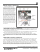
ATTENTION:
to service the heater. Bear in mind that all of the components that comprise the system have an effect
piping are properly positioned, and the time clocks are properly set.
WARNING: EXPLOSION HAZARD Do not attempt to repair any components of
this heater. Do not modify the heater in any manner. To do so may result in a mal-
the consumer to see if any part of the heater has been under water. Replace any part
of the control system and any gas control that has been under water.
MAINTENANCE:
The following inspection procedures are recommended to be performed as part of annual heater mainte-
nance and to ensure safe operation.
1. External heat exchanger
2. Internal heat exchanger
5. Operating controls
Inspection procedures are covered below. Some of the procedures will require disconnecting and remov-
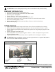
CONTROL ACCESS:
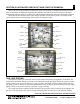
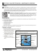
To access the operating controls as shown in Figure 37:
1. Remove the (4) screws from the front access panel.
2. Label all wires prior to discon-
nection when servicing controls.
3. If there are questions when re-
connecting the wires, refer to the
wiring diagram in Figure 28.
servicing.
5. After service is complete, as-
sembly is the reverse of Steps 1-2
above.
Figure 37: Panel removal for various maintenance procedures.
(Note: not all panels need be removed for every procedure, follow
the written instructions in Section VI.)
Top panel
Flue cover
Heat exchanger
Water header
Header side
trim panel
End cap
Side jacket
Control boards
Rain shield
assembly
Flue collector
panel (2)
Blank side
trim panel
End cap
Front access
panel