
Instructions / Assembly

USE ONLY HAYWARD GENUINE REPLACEMENT PARTS 5
2. General Information
2.1. Introduction
This manual contains information for the proper installation and operation of the Hayward MaxFlo XL Series. The
instructions in this manual MUST be followed precisely. Failure to install according to defined instructions will
void warranty.
2.2. Primary Features
• Aligns with the original MaxFlo pump for seamless retrofit installations.
• Advanced hydraulics for increased efficiency and priming ability.
• All models include 1 1/2” x 2” union connections.
• See-through strainer cover lets you see when the basket needs cleaning and seals with less than a quarter turn.
• Pressure testable to 50 psi maximum.
• Optional riser base available to align with Sta-Rite® Dyna-Pro®.
• Self-priming (suction lift up to 8’ above water level)
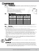
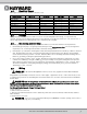
2.3. Product Dimensions
3. Installation and Wiring
WARNING – This product should be installed and serviced only by a qualified professional.
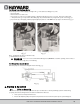
3.1. Pump Location
WARNING – Fire and burn hazard. Motors operate at high temperatures and if they are not
properly isolated from any flammable structures or foreign debris they can cause fires, which may cause
severe personal injury or death. It is also necessary to allow the motor to cool for at least 20 minutes prior
to maintenance to minimize the risk for burns.
Locate pump as close to pool as practical and run suction lines as direct as possible to reduce friction loss. Pump
height location should be as close to pool water level as possible and NOT to exceed 8 feet. Suction lines should
have continuous slope upward from lowest point in line. Joints must be tight (but not over-tightened). Suction line
diameter must equal or be larger than the discharge line diameter.
Though the pump is designed for outdoor use, it is advised to place pump and filter in the shade
to shield them from continuous direct heat. Select a well-drained area that will not flood when it
rains. Do NOT install pump and filter in a damp or non-ventilated location. Keep motor clean.
Pump motors require free circulation of air for cooling.
Single Speed
HP Dim "A"
0.75 10.8"
1 11.3"
1.5 12.4"
2 12.5"
Dual Speed
HP Dim "A"
1 12.0"
1.5 12.5"
2 13.0"