® Model No. 831.159710 Serial No. USER'S MANUAL (Write the serial number in the space above for reference.) Serial Number Decal (under seat) SEARS, ROEBUCK AND CO. HOFFMAN ESTATES, IL 60179 CAUTION Read all precautions and instructions in this manual before using this equipment. Save this manual for future reference. Visit our website at www.weiderfitness.
TABLE OF CONTENTS FULL 90-DAY WARRANTY . . . . . . . . . . . . . . . . . . . . . . . . . . . . . . . . . . . . . . . . . . . . . . . . . . . . . . . . . . . . . . .2 IMPORTANT PRECAUTIONS . . . . . . . . . . . . . . . . . . . . . . . . . . . . . . . . . . . . . . . . . . . . . . . . . . . . . . . . . . . . .3 BEFORE YOU BEGIN . . . . . . . . . . . . . . . . . . . . . . . . . . . . . . . . . . . . . . . . . . . . . . . . . . . . . . . . . . . . . . . . . . .4 ASSEMBLY . . . . . . . . . . . . . . . . . . . .
IMPORTANT PRECAUTIONS WARNING: To reduce the risk of serious injury, read the following important precautions before using the home gym. 1. Read all instructions in this manual and in the accompanying literature before using the home gym. weight carriage. 13. Always disconnect the lat bar from the home gym when performing an exercise that does not use the lat bar. 2. It is the responsibility of the owner to ensure that all users of the home gym are adequately informed of all precautions. 14.
BEFORE YOU BEGIN HELPLINE at 1-800-736-6879, Monday through Saturday, 7 a.m. until 7 p.m. Central Time (excluding holidays). To help us assist you, please note the product model number and serial number before calling. The model number is 831.159710. The serial number can be found on a decal attached to the WEIDER® 8920 (see the front cover of this owner's manual). Thank you for selecting the versatile WEIDER® 8920 home gym.
ASSEMBLY Before beginning assembly, carefully read the following information and instructions: • As you assemble the home gym, be sure that all parts are oriented as shown in the drawings. • Place all parts of the home gym in a cleared area and remove the packing materials; do not dispose of the packing materials until assembly is completed. • Tighten all parts as you assemble them, unless instructed to do otherwise.
2. Refer to drawing 2a. Press a 1” Inner Cap (61) into each end of the weight tube on the Weight Carriage (19). Note: The Square Slider Bushings (70) should be pre-assembled to the Weight Carriage (19) and Weight Stop (67). 19 61 19 70 61 70 67 Turn the Weight Stop (67) so that the hole in the Weight Stop is oriented in the same direction as the hole in the bottom of the Rear Upright (56). Make sure that the Square Slider Bushing (70) is above the Weight Stop.
5. Press a 1 3/4” Square Inner Cap (44) into the top of one of the Press Arms (46). Press a 1” Round Inner Cap (49) into each end of the handle on the Press Arm. Attach the Press Arm to one side of the Press Frame (17) with two 5/16” x 2 1/2” Bolts (22) and two 5/16” Nylon Locknuts (3). 5 44 49 44 49 49 46 Assemble the other Press Arm (46) in the same manner. 46 22 3 17 6. Identify the Right Arm (48) and the Left Arm (47). Note the position of the welded bracket on each Arm.
. During steps 9 through 22, refer to the CABLE DIAGRAM on page 19 of this manual to verify proper cable routing. Before beginning this section, identify the Short Cable (23) and the Long Cable (58) by comparing the lengths and the ends of the cables. 8 23 IMPORTANT: While assembling the cables, do not overtighten the bolts and nuts securing the pulleys. The pulleys must turn freely. CABLE ASSEMBLY 9. Locate the Long Cable (58). Route the Long Cable around a 3 1/2” Pulley (15).
12. Route the Long Cable (58) around a “V”Pulley (6). Be sure that the Cable is in the groove of the “V”-Pulley and that a Long Cable Trap (50) is turned to hold the Cable in place. 12 6 Attach the “V”-Pulley (6) and the Long Cable Trap (50) to the Right Arm (48) with a 3/8” x 2 1/2” Bolt (7) and a 3/8” Nylon Locknut (21). Make sure the Bolt and Nylon Locknut are tight. CABLE ASSEMBLY 13. Refer to the inset drawing.
16. Attach the Long Cable (58) to the Weight Carriage (19) with a 3/8” x 3/4” Bolt (69) and a 3/8” Nylon Locknut (21). Make sure that the Bolt and the Nylon Locknut are tight. 16 58 21 CABLE ASSEMBLY 19 69 17. Using a 3/8” x 3 1/2” Bolt (16), a 3/8” Flat 17 Washer (9), and a 3/8” Nylon Locknut (21), secure a 3 1/2” Pulley (15) and a Cable Trap (66) to the upper hole in the Press Frame (17). Make sure that the Cable Trap and the Pulley are oriented as shown.
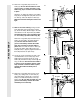
19. Slide a Cable Trap (66) and a 3 1/2” Pulley (15) onto each 3/8” x 3 3/4” Bolt (68). Insert the Bolts into the Front Upright (42) from the direction shown. Hand tighten a 3/8” Nylon Locknut (21) with a 3/8” Flat Washer (9) onto each Bolt. Be sure that all parts are oriented as shown. Do not tighten the Nylon Locknuts yet. 19 66 42 68 15 9 15 21 CABLE ASSEMBLY 20. Route the Short Cable (23) around the 3 1/2” Pulley (15) attached to the lower hole in the Front Upright (42). See the inset drawing.
22. Attach the end of the Short Cable (23) to the Long “U”-Bracket (57) with a 1/4” Nylon Locknut (2) and a 1/4” Flat Washer (10). Do not completely tighten the Nylon Locknut; it should be threaded onto the end of the Cable until two threads are showing above the Nylon Locknut, as shown in the inset drawing. 22 CABLE ASSEMBLY 2 57 10 23 2 10 57 23. Attach the Backrest (41) to the Front Upright (42) with two 1/4” x 2 1/2” Screws (43) and two 1/4” Flat Washers (10).
24. Press a 1 1/2” Square Inner Cap (32) into the Seat Frame (36). 24 Insert the 1/4” x 2” Carriage Bolt (38) into the center hole in the Seat Plate (37). Attach the Seat Plate to the Seat (13) with two 1/4” x 3/4” Screws (18). 13 Insert the 1/4” x 2” Carriage Bolt (38) into the indicated hole in the Seat Frame (36). Tighten a 1/4” Nylon Locknut (2) with a 1/4” Flat Washer (10) onto the Carriage Bolt.
27. Press 3/4” Round Inner Caps (34) into the ends of both Pad Tubes (28). 27 SEAT ASSEMBLY Insert one Pad Tube (28) into the Seat Frame (36). Slide a Foam Pad (30) onto each end of the Pad Tube. Insert the other Pad Tube (28) into the Leg Lever (29). Slide a Foam Pad (30) onto each end of the Pad Tube. 36 34 30 28 34 30 29 28. Make sure that all parts have been properly tightened. The use of all remaining parts will be explained in ADJUSTMENT, beginning on page 15 of this manual.
ADJUSTMENT The instructions below describe how each part of the home gym can be adjusted. Refer to the exercise poster accompanying this manual to see how the home gym should be set up for each exercise. IMPORTANT: When attaching the lat bar or nylon strap, make sure that the attachments are in the correct starting position for the exercise to be performed. If there is any slack in the cables or chain as an exercise is performed, the effectiveness of the exercise will be reduced.
ATTACHING AND REMOVING THE SEAT 40 Set the bracket on the Seat Frame (36) onto the indicated pins on the Front Upright (42). Attach the Seat Frame to the Front Upright with the 5/16” x 2 3/4” Carriage Bolt (14) and the Seat Knob (40). 13 36 42 14 For some exercises, the Seat (13) must be removed. First, be sure that the chain is not attached to the leg lever. Next, remove the Seat Knob (40) and the 5/16” x 2 3/4” Carriage Bolt (14) from the Seat Frame (36).
WEIGHT RESISTANCE CHART This chart shows the approximate weight resistance at each weight station. The column labeled “WEIGHT ON WEIGHT CARRIAGE” refers to the amount of weight, in pounds, placed on the weight carriage. The weight resistance shown for the butterfly arm station is for each butterfly arm. Note: The actual resistance at each station may vary due to friction between the cables, pulleys, and weight carriage. WEIGHT ON WEIGHT CARRIAGE PRESS ARM (lbs.) BUTTERFLY ARM (lbs.
TROUBLE-SHOOTING AND MAINTENANCE Inspect and tighten all parts each time you use the home gym. Replace any worn parts immediately. The home gym can be cleaned using a damp cloth and mild non-abrasive detergent. Do not use solvents. TIGHTENING THE CABLES Woven cable, the type of cable used on the home gym, can stretch slightly when it is first used. If there is slack in the cables before resistance is felt, the cables should be tightened.
CABLE DIAGRAM The cable diagram below shows the proper routing of the Short Cable (23) and the Long Cable (58). Use the diagram to be sure that the two cables and the cable traps have been assembled correctly. If the cables have not been correctly routed, the home gym will not function properly and damage may occur. The numbers show the correct route for each cable. The starting and ending points of each cable are labeled. The small drawings show the correct position of each cable trap.
831.
1" x 7/8" Plastic Bushing (26) 1" Retainer (63) 3/8" x 3/4" Bolt (69) 3/8" x 1 3/4" Bolt (71) 3/8" x 2" Bolt (12) 3/8" x 2 1/2"Bolt (7) 3/8" x 3 1/2" Bolt (16) 3/8" x 3 3/4" Bolt (68) 3/8" x 8" Bolt (59) Cable Clip (53)
3/4" Round Inner Cap (34) 1" Round Inner Cap (49) 1" Round Cover Cap (62) 3/8" x 2 1/2" Eyebolt (35) 1" Inner Cap (61) 1" Square Inner Cap (65) 1 3/4" Square Inner Cap (44) 1 1/2" Square Inner Cap (32) 2" Square Inner Cap (27) 2" Square Outer Cap (51)
PART LIST—Model No. 831.159710 Key No. Qty. 1 2 3 4 5 6 7 8 9 10 11 12 13 14 15 16 17 18 19 20 21 22 23 24 25 26 27 28 29 30 31 32 33 34 35 36 37 2 2 14 1 1 3 3 4 6 5 3 2 1 3 8 2 1 2 1 1 13 6 1 1 1 2 2 2 1 4 2 2 1 4 1 1 1 Description R0801A Key No. Qty.
EXPLODED DRAWING—Model No. 831.
Model No. 831.159710 QUESTIONS? If you find that: The model number and serial number of your WEIDER® 8920 home gym are listed on a decal attached to the frame. See the front cover of this manual to find the location of the decal. All replacement parts are available for immediate purchase or special order when you visit your nearest SEARS Service Center. To request service or to order parts by telephone, call the toll-free numbers listed at the left.