Model No. 831.287940 Serial No. USER'S MANUAL The serial number can be found in the location shown below. Write the serial number in the space above. Serial Number Decal QUESTIONS? PLEASE CALL DIRECT TO OUR TOLL-FREE CUSTOMER HOT LINE. The trained technicians on our customer hot line will provide immediate assistance, free of charge. CUSTOMER HOT LINE: 1-800-999-3756 Mon.–Fri., 6 a.m.–6 p.m. MST Patent Pending CAUTION Read all precautions and instructions in this manual before using this equipment.
TABLE OF CONTENTS IMPORTANT PRECAUTIONS . . . . . . . . . . . . . . . . . . . . . . . . . . . . . . . . . . . . . . . . . . . . . . . . . . . . . . . . . . . . .2 BEFORE YOU BEGIN . . . . . . . . . . . . . . . . . . . . . . . . . . . . . . . . . . . . . . . . . . . . . . . . . . . . . . . . . . . . . . . . . . .3 ASSEMBLY . . . . . . . . . . . . . . . . . . . . . . . . . . . . . . . . . . . . . . . . . . . . . . . . . . . . . . . . . . . . . . . . . . . . . . . . . . .4 ADJUSTMENT AND OPERATION . . . . . .
BEFORE YOU BEGIN Time (excluding holidays). To help us assist you, please note the product model number and serial number before calling. The model number is 831.287940. The serial number can be found on a decal attached to the AEROBIC RIDER 2® (see the front cover of this manual). Thank you for selecting the new AEROBIC RIDER 2® by HEALTHRIDER®.
ASSEMBLY Before beginning assembly, carefully read the following information and instructions: • Tighten all parts as you assemble them, unless instructed to do otherwise. • Place all parts in a cleared area and remove the packing materials; do not dispose of the packing materials until assembly is completed. • During assembly, make sure that all parts are oriented as shown in the drawings. THE FOLLOWING TOOLS (NOT INCLUDED) ARE REQUIRED FOR ASSEMBLY: • Read each assembly step before you begin.
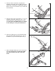
1. Before beginning assembly, be sure that you have read and understand the information on the previous page. 1 Attach the Front Stabilizer (28) to the Main Frame (47) with four M6 X 40mm Bolts (60), eight 1/4” Flat Washers (57), and four M6 Hex Nuts (2). 2 57 47 2 57 60 57 57 60 28 2. Attach the Rear Stabilizer (25) to the Main Frame (47) with two M6 X 40mm Bolts (60), four 1/4” Flat Washers (57), and two M6 Hex Nuts (2). 2 25 60 57 57 47 2 3. Lubricate a M8 x 157mm Axle (59).
4. Lubricate a M8 x 157mm Axle (59). Attach the Handlebar Swing Arm (29) to the Main Frame (47) with the M8 x 157mm Axle, two M9 Rubber Shield Washers (58), two 5/16” Washers (55), and two M8 Acorn Nuts (56). 4 29 56 58 47 55 58 55 Lubricate—59 56 5. Attach the Short and Long Link Arms (11, 12) to the Handlebar Swing Arm (29) with the 3/8” x 1 3/8” Shoulder Bolt (61), and the M8 Nylon Lock Nut (31). Note: Part of the Main Frame is not shown in this drawing for easier part indentification.
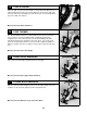
8. Insert the Seat (17) into the Weight Saddle (34). Slide the Large Washer (19) onto the Seat Bolt (51). Tighten the Seat Knob (18) onto the Seat Bolt until the Washer is secure against the Seat Frame (48). 8 17 51 19 34 48 18 9. Insert the Weight Bar (32) through the Weight Saddle (34). Center the Weight Bar in the Weight Saddle. Thread the Weight Bar Screw (54) fully into the drilled hole in the Weight Saddle to secure the Weight Bar.
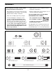
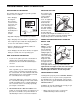
ADJUSTMENT AND OPERATION DESCRIPTION OF THE MONITOR ADJUSTING THE SEAT The monitor offers five modes to provide you with instant exercise feedback: The position of the seat can be adjustSeat ed to accommoKnob date different users. To adjust the seat, loosen the knob under the seat, move the seat to the desired position, and retighten the knob. To determine if the seat is properly adjusted, sit on the seat and pull the handlebar as close as possible to your stomach.
• You should be able to feel yourself pivot or bend from the hip, not from the back. Don’t round your back as the bar moves forward. your back becomes stronger and more flexible, allow the handlebar to travel farther forward for increased range-of-motion. • Always place the ball of each foot in the center of each pedal. • Change grip positions and toe positions often to add variety and balance to each workout. • Always bring the handlebar as close to your stomach or rib cage as possible.
4 TOES STRAIGHT Place the ball of each foot in the middle of each pedal. Push with your toes pointed forward, then pull your feet back with toes up and heels down. This tones the lower legs. Start with just a few minutes per session and gradually increase with each workout. Muscles affected: Shins and Calves 5 TOES TURNED The direction which your toes are turned will vary the effect of your workout. If your toes are turned slightly in while pointing and flexing, this emphasizes the outer calves.
MAINTENANCE AND TROUBLE-SHOOTING Inspect and tighten all parts of the AEROBIC RIDER 2® by HEALTHRIDER® regularly. Keep the monitor out of direct sunlight or the display may be damaged. The AEROBIC RIDER 2® can be cleaned with a soft, damp cloth. Do not use solvents. Keep liquid away from the monitor. When storing the AEROBIC RIDER 2®, remove the battery from the monitor. HOW TO REPLACE THE BATTERIES If the display of the monitor becomes dim, the AAA battery should be replaced.
CONDITIONING GUIDELINES The following general guidelines will help you to plan your exercise program. Remember that proper nutrition and adequate rest are essential for successful results. gy. Only after the first few minutes of exercise does your body begin to use stored fat calories for energy. If your goal is to burn fat, adjust your pace until your heart rate is near the lowest number in your training zone as you exercise. WARNING: Before beginning this or any exercise program, consult your physician.
Training zone exercise, consisting of 20 to 30 minutes of exercising with your heart rate in your training zone. (See the chart on page 12 to find your training zone.) leave you relaxed and comfortably tired. EXERCISE FREQUENCY To maintain or improve your condition, plan three workouts each week, with at least one day of rest between workouts. After a few months of regular exercise, you may complete up to five workouts each week, if desired.
Part No. 130312 012006 133719 133720 133579 133704 133616 133957 133819 133581 133823 133822 133703 133931 133932 133636 133702 133699 133615 133633 133827 133826 103957 133634 133667 133834 133233 133715 133831 133830 012002 Key No. 1 2 3 4 5 6 7 8 9 10 11 12 13 14 15 16 17 18 19 20 21 22 23 24 25 26 27 28 29 30 31 2 6 2 2 5 1 6 1 1 5 1 1 1 1 1 2 1 1 1 2 1 1 4 2 1 1 1 1 1 1 4 Qty.
24 56 59 5 60 13 20 54 55 58 40 57 16 28 57 44 36 30 10 57 15 37 9 57 20 31 41 10 7 11 60 24 7 58 4 41 57 58 2 7 3 61 2 57 29 38 58 57 23 56 55 58 59 57 16 36 7 23 5 41 56 55 14 6 40 21 43 31 46 41 58 55 56 46 EXPLODED DRAWING—Model No. 831.
HOW TO ORDER REPLACEMENT PARTS To order replacement parts, simply call our Customer Service Department toll-free at 1-800-999-3756, Monday through Friday, 6 a.m. until 6 p.m. Mountain Time (excluding holidays). To help us assist you, please be prepared to give the following information when calling: • The MODEL NUMBER of the product (831.287940). • The NAME of the product (AEROBIC RIDER 2® by HEALTHRIDER®). • The PART NUMBER of the PART (see pages 14 and 15 of this manual).