Model No. HRCCEL59930 Serial No. _ USER’S MANUAL Serial Number Decal (underneath frame) QUESTIONS? As a manufacturer, we are committed to providing complete customer satisfaction. If you have questions, or if there are missing parts, please call: 1-888-936-4266 Mon.–Fri. 8h00 until 18h30 EST (excluding holidays). CAUTION Read all precautions and instructions in this manual before using this equipment. Keep this manual for future reference. Visit our website at www.healthrider.
TABLE OF CONTENTS IMPORTANT PRECAUTIONS . . . . . . . . . . . . . . . . . . . . . . . . . . . . . . . . . . . . . . . . . . . . . . . . . . . . . . . . . . . . . . . .3 BEFORE YOU BEGIN . . . . . . . . . . . . . . . . . . . . . . . . . . . . . . . . . . . . . . . . . . . . . . . . . . . . . . . . . . . . . . . . . . . . . .4 ASSEMBLY . . . . . . . . . . . . . . . . . . . . . . . . . . . . . . . . . . . . . . . . . . . . . . . . . . . . . . . . . . . . . . . . . . . . . . . . . . . . . . .
IMPORTANT PRECAUTIONS WARNING: To reduce the risk of serious injury, read the following important precautions before using the elliptical exerciser. 1. Read all instructions in this manual before using the elliptical exerciser. 12. The pulse sensor is not a medical device. Various factors, including the user's movement, may affect the accuracy of heart rate readings. The pulse sensor is intended only as an exercise aid in determining heart rate trends in general. 2.
BEFORE YOU BEGIN Congratulations for selecting the new HealthRider® AIRE STRIDER E60 elliptical exerciser. The AIRE STRIDER E60 is an incredibly smooth exerciser that moves your feet in a natural elliptical path, minimizing the impact on your knees and ankles. And the unique AIRE STRIDER E60 features adjustable resistance and incline to help you get the most from your exercise. Welcome to a whole new world of natural, ellipticalmotion exercise from HealthRider.
ASSEMBLY Assembly requires two persons. Place all parts of the elliptical exerciser in a cleared area and remove the packing materials. Do not dispose of the packing materials until assembly is completed. In addition to the , two adjustable included allen wrenches, assembly requires a phillips screwdriver wrenches , a rubber mallet , and pliers . As you assemble the elliptical exerciser, use the drawings below to identify the small parts used for assembly.
2. Identify the Pivot Axle (14), which is the longest axle. Slide a Ramp Cover (48) onto an M6 x 16mm Patch Screw (76) as shown. Tighten the Patch Screw into one end of the Pivot Axle. Apply a small amount of the included grease to the Pivot Axle. 2 48 76 Tubes Have a second person hold the two Ramp Spacers (99) against the sides of the Frame (1) so they cover the indicated tubes on the Frame.
5. Apply a small amount of grease to the axle on the Left Crank Arm (34). 5 Grease Identify the Left Pedal Leg (4), which is marked with an “L” sticker. Slide the Left Pedal Leg onto the axle on the Left Crank Arm (34). (Note: It may be helpful to use a rubber mallet to tap the Left Pedal Leg on. Do not confuse the Left Pedal Leg with the Right Pedal Leg [not shown].) Attach the Left Pedal Leg with an M8 x 19mm Patch Screw (111), an M8 Washer (66), and a Torque Washer (113).
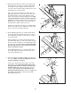
7. Apply a small amount of the included Teflon® lubricant to a paper towel. Rub a thin film of the lubricant onto each Upper Body Leg (31). 7 Identify the Left Upper Body Arm (112), which is marked with an “L” sticker. Slide the Left Upper Body Arm onto the left Upper Body Leg (31). Slide the Right Upper Body Arm (118) onto the right Upper Body Leg (not shown). Make sure that the Upper Body Arms are on the correct sides. Next, slide an Axle Cover (26) onto the post on each Upper Body Arm.
. Have another person hold the Console (17) near the Upright (2). Connect the Upper Wire Harness (95) to the wire harness on the Console (17). Connect the Pulse Extension Wire (101) to the pulse wire on the Console. Next, locate the two ground wires that are attached to the Upright (2). Connect the two ground wires to the two smallest wires on the Console. 9 Do not pinch the wires during this step. 101 98 Carefully insert all excess wiring up into the Console (17) and down into the Upright (2).
HOW TO USE THE ELLIPTICAL EXERCISER HOW TO PLUG IN THE POWER CORD The green-colored rigid ear, lug, or the like extending from the adapter must be connected to a permanent ground such as a properly grounded outlet box cover. Whenever the adapter is used, it must be held in place by a metal screw. Some 2-pole receptacle outlet box covers are not grounded. Contact a qualified electrician to determine if the outlet box cover is grounded before using an adapter.
CONSOLE DIAGRAM Left Display Matrix Training Zone Bar Note: If there are sheets of clear plastic on the face of the console, remove the plastic. FEATURES OF THE CONSOLE The advanced console offers a selection of features designed to make your workouts more enjoyable and effective. When the manual mode of the console is selected, the resistance of the elliptical exerciser and the angle of the ramp can be changed with the touch of a button.
5 HOW TO USE THE MANUAL MODE 1 The matrix— When the manual mode or the iFIT.com mode is selected, the matrix will show a track representing 440 revolutions (a distance of approximately 1/4 mile). As you exercise, the indicators around the track will light in succession until the entire track is lit. The track will then darken and the indicators will again begin to light in succession. Press any button on the console or begin pedaling to turn on the console.
Note: The console can show the total number of hours that the elliptical exerciser has been used and the total number of revolutions pedaled. To view this information, hold down the Program button for about three seconds. The left display will show the total number of hours that the elliptical exerciser has been used. Press the Start button. The left display will then show the total number of revolutions pedaled, divided by 100 (for example, the number 96 in the display equals to 9,600 revolutions).
series of tones will sound, and all resistance settings will move one column to the left. The resistance setting for the second segment will then be shown in the flashing Current Segment column and the resistance of the elliptical exerciser will automatically change to the resistance setting for the second segment.
4 Adjust the angle of the ramp as desired. HOW TO USE HEART RATE PROGRAMS See step 4 on page 12. 5 See step 6 on page 13. Heart rate program 7 is designed to keep your heart rate between 50% and 85% of your estimated maximum heart rate during your workout. (Your maximum heart rate is estimated by subtracting your age from 220. For example, if you are 30 years old, your estimated maximum heart rate is 190.
If you have selected heart rate program 8, the letters “PLS” and the current target heart rate setting will flash in the left display. Press the – and + buttons repeatedly to change the target heart rate setting, if desired. The target heart rate setting can be from 70 to 170 beats per minute. 4 As you exercise, a the Training Zone bar will help you to keep your heart rate near the current target heart rate setting. The lit b indicators in the bar will show your actual pace.
HOW TO CONNECT YOUR PORTABLE STEREO HOW TO CONNECT YOUR CD PLAYER, VCR, OR COMPUTER Note: If your stereo has an RCA-type AUDIO OUT jack, see instruction A below. If your stereo has a 1/8” LINE OUT jack, see instruction B. If your stereo has only a PHONES jack, see instruction C. To use iFIT.com CDs, the elliptical exerciser must be connected to your portable CD player, portable stereo, home stereo, or computer with CD player. See pages 17 to 18 for connecting instructions. To use iFIT.
HOW TO CONNECT YOUR HOME STEREO HOW TO CONNECT YOUR COMPUTER Note: If your stereo has an unused LINE OUT jack, see instruction A below. If the LINE OUT jack is being used, see instruction B. Note: If your computer has a 1/8” LINE OUT jack, see instruction A. If your computer has only a PHONES jack, see instruction B. A. Plug one end of a 1/8” to RCA stereo audio cable (available at electronics stores) into the jack beneath the console.
HOW TO CONNECT YOUR VCR B. Plug one end of a 1/8” to RCA stereo audio cable (available at electronics stores) into the jack beneath the console. Plug the other end of the cable into an RCA Y-adapter (available at electronics stores). Next, remove the wire that is currently plugged into the AUDIO OUT jack on your VCR and plug the wire into the unused side of the Yadapter. Plug the Y-adapter into the AUDIO OUT jack on your VCR. Note: If your VCR has an unused AUDIO OUT jack, see instruction A below.
your workout. Simply follow your personal trainer’s instructions. HOW TO USE IFIT.COM CD AND VIDEO PROGRAMS The program will function in almost the same way as a resistance and pace program (see step 3 on page 14). However, an electronic “chirping” sound will alert you when the resistance setting and/or the pace setting is about to change. To use iFIT.
7 HOW TO USE PROGRAMS DIRECTLY FROM OUR WEB SITE When the on-screen countdown ends, the program will begin. The program will function in almost the same way as a resistance and pace program (see step 3 on page 14). However, an electronic “chirping” sound will alert you when the resistance setting and/or the pace setting is about to change. Our Web site at www.iFIT.com allows you to play iFIT.com audio and video programs directly from the internet.
MAINTENANCE AND TROUBLESHOOTING HOW TO MOVE THE ELLIPTICAL EXERCISER Inspect and properly tighten all parts of the elliptical exerciser regularly. Replace any worn parts immediately. Stand in front of the elliptical exerciser, hold the handlebars firmly, and place one foot against the ramp in the location shown below. Pull the handlebars until the elliptical exerciser can be moved on the front wheels, and carefully move the elliptical exerciser to the desired location.
CONDITIONING GUIDELINES During the first few minutes of exercise, your body uses easily accessible carbohydrate calories for energy. Only after the first few minutes of exercise does your body begin to use stored fat calories for energy. If your goal is to burn fat, adjust the intensity of your exercise until your heart rate is near the lowest number in your training zone as you exercise. WARNING: Before beginning this or any exercise program, consult your physician.
PART LIST—Model No. HRCCEL59930 R0904A To locate the parts listed below, see the EXPLODED DRAWING on pages 26 and 27. Key No. Qty. 1 2 3 4 5 6 7 8 9 10 11 12 13 14 15 16 17 18 19 20 21 22 23 24 25 26 27 28 29 30 31 32 33 34 35 36 37 38 39 40 41 42 43 44 45 46 47 48 49 50 51 52 1 1 1 1 1 1 2 1 2 1 1 1 1 1 1 1 1 2 1 2 1 1 1 1 1 2 1 2 4 2 2 1 4 1 1 1 1 1 1 1 1 1 1 2 1 2 4 2 1 1 2 1 Description Key No. Qty.
Key No. Qty. 105 106 107 108 109 110 111 112 113 2 2 2 1 2 4 2 1 2 Description Key No. Qty. M8 x 35mm Button Bolt Upper Foam Grip Lower Foam Grip M4 x 63.5mm Tek Screw Wheel Wheel Bushing M8 x 19mm Patch Screw Left Upper Body Arm Torque Washer 114 115 116 117 118 119 # # 3 2 2 2 1 2 Description M10 x 25mm Button Screw M10 x 105 Carriage Bolt M4 x 58mm Screw Incline Motor Bushing Right Upper Body Arm Outer Pedal Leg Bushing Allen Wrench User’s Manual Note: # indicates a non-illustrated part.
24 105 84 98 20 68 87 86 91 81 90 81 112 85 17 25 81 110 80 26 86 85 29 28 29 26 81 86 2 110 114 31 57 98 96 84 114 57 114 118 80 81 110 81 To identify the parts shown below, see the PART LIST on pages 24 and 25. 31 110 98 15 101 19 29 29 28 90 91 95 20 98 68 105 23 EXPLODED DRAWING—Model No.
65 9 33 33 83 67 63 65 76 89 10 109 8 4 76 83 48 64 67 9 47 66 111 3 50 49 47 119 12 75 113 47 13 51 48 73 64 76 89 82 34 14 76 72 117 104 38 99 55 53 30 117 97 54 36 65 74 27 88 30 99 93 43 11 58 71 37 60 98 45 89 88 89 65 33 42 77 44 7 70 1 89 79 52 89 32 88 71 88 78 61 100 79 59 103 62 60 83 51 89 92 94 98 39 94 46 7 73 119 111 102 82 66 113 98 21 115 Model No.
HOW TO ORDER REPLACEMENT PARTS To order replacement parts, call our customer service department toll-free at 1-888-936-4266, Monday through Friday 8h00 until 18h30 eastern time (excluding holidays).