Model No. HRE99940 Serial No. USER'S MANUAL Serial Number Decal (underneath frame) QUESTIONS? If you have questions, or if there are missing parts, we will guarantee complete satisfaction through direct assistance from our factory. TO AVOID DELAYS, PLEASE CALL DIRECT TO OUR TOLLFREE CUSTOMER HOT LINE. The trained technicians on our customer hot line will provide immediate assistance, free of charge to you. CUSTOMER HOT LINE: 1-888-922-4222 Mon.-Fri., 6 a.m.-6 p.m.
TABLE OF CONTENTS IMPORTANT PRECAUTIONS ................................................................ BEFORE YOU BEGIN ...................................................................... ASSEMBLY ............................................................................... HOW TO USE THE CHEST PULSE SENSOR .................................................. HOW TO USE THE ELLIPTICAL EXERCISER .................................................. MAINTENANCE AND TROUBLESHOOTING ..........................
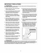
IMPORTANT PRECAUTIONS _ WARNING: To reduce the risk of serious injury, read the following important precau- tions before using the elliptical exerciser. 1. Read all instructions in this manual before using the elliptical exerciser. 2. It is the responsibility of the owner to ensure that all users of the elliptical exerciser are adequately informed of all precautions, 3. The elliptical exerciser is intended for in-home use only.
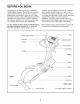
BEFORE YOU BEGIN Congratulations for selecting the new HealthRider _ C895e elliptical exerciser. The C895e is an incredibly smooth exerciser that moves your feet in a natural elliptical path, minimizing the impact on your knees and ankles. And the unique C895e features adjustable resistance and incline to help you get the most from your exercise. Welcome to a whole new world of natural, elliptical-motion exercise from HealthRider.
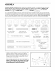
ASSEMBLY Assembly requires two persons. Place all parts of the elliptical exerciser in a cleared area and remove the packing materials. Do not dispose of the packing materials until assembly is completed. In addition to the included allen wrenches, assembly requires a phillips screwdriver ___ _, two adjustable wrenches _, a rubber mallet C_7 _ , and pliers As you assemble the elliptical exerciser, use the drawings below to identify the small parts used for assembly.
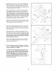
2. Identifythe PivotAxle(14),whichis thelongestaxle. Slidea RampCover(48)ontoan M6x 16mmPatch Screw(76)as shown.TightenthePatchScrewinto oneendofthePivotAxle.Applya smallamountof the includedgreasetothePivotAxle. 48 Havea secondpersonholdthetwoRampSpacers (99)againstthesidesofthe Frame(1)so theycover theindicatedtubesontheFrame.Aligntheround tubesontheRamp(3)withtheRampSpacers;make sure that the Ramp is turned as shown in drawing 3 below.
5. Apply a small amount of grease to the axle on the Left Crank Arm (34). Grease Identify the Left Pedal Leg (4), which is marked with an "L" sticker. Slide the Left Pedal Leg onto the axle on the Left Crank Arm (34). (Note: It may be helpful to use a rubber mallet to tap the Left Pedal Leg on. Do not to confuse the Left Pedal Leg with the Right Pedal Leg [not shown].) Attach the Left Pedal Leg with an M8 x 19mm Patch Screw (111), an M8 Washer (66), and a Torque Washer (113).
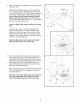
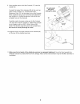
7. Applya smallamountoftheincludedTeflon ®lubricant toa papertowel.Ruba thinfilmofthelubricantonto eachUpperBodyLeg(31). Identifythe LeftUpperBodyArm(112),whichis markedwithan"L"sticker.Slidethe LeftUpperBody ArmontotheleftUpperBodyLeg(31).Slidethe Right UpperBodyArm(118)ontotherightUpperBodyLeg (notshown).Make sure that the Upper Body Arms 2 // \\ \\ \ are on the correct sides. Next, slide an Axle Cover (26) onto the post on each Upper Body Arm. // Hole 26 Apply grease to the Arm Axle (19).
. HaveanotherpersonholdtheConsole(17)nearthe Upright(2). ConnecttheUpperWireHarness(95)to thewireharnessonthe Console(17).ConnectthePulse Extension Wire(101) tothe pulsewireontheConsole. Next,locatethetwogroundwiresthatareattachedto the Upright(2).Connectthegroundwirestothetwo smallestwireson theConsole. 9 Do not pinch the wires during this step. 101 98 CarefullyinsertallexcesswiringupintotheConsole (17)anddownintotheUpright(2).AttachtheConsole tothe UprightwithfourM4x 16mmScrews(98).
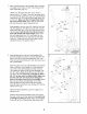
HOW TO USE THE CHEST PULSE SENSOR To get the best performance from the chest pulse sensor, please read the instructions below. two electrode areas on the inner side. Using a saline solution such as saliva or contact lens solution, wet both electrode areas. Return the sensor unit to a position against your chest. HOW TO PUT ON THE CHEST PULSE SENSOR CHEST PULSE SENSOR TROUBLESHOOTING The chest pulse sensor consists of two components: the chest strap and the sensor unit.
CHESTPULSESENSOR Next, hold the chest pulse sensor near the console. While holding one thumb stationary, begin tapping the other thumb against the electrode area at a rate of about one tap per second. Check the heart rate reading on the console. Thoroughly dry the chest pulse sensor after each use. The chest pulse sensor is activated when the electrode areas are wetted and the chest pulse sensor is put on; the chest pulse sensor shuts off when it is removed and the electrode areas are dried.
HOW TO USE THE ELLIPTICAL HOW TO PLUG IN THE POWER CORD The green-colored rigid ear, lug, or the like extending from the adapter must be connected to a permanent ground such as a properly grounded outlet box cover. Whenever the adapter is used, it must be held in place by a metal screw. Some 2-pole receptacle outlet box covers are not grounded. Contact a qualified electrician to determine if the outlet box cover is grounded before using an adapter. This product must be Grounded Outlet Box grounded.
CONSOLE DIAGRAM RESISTANCE / PACE PROGRAMS Left Display Matrix Training Zone Bar I !l c:_ RAMP c= TOTALREVS, _ .......... _ CAT_ CALS _ RESISTAI/CE 10 _ r
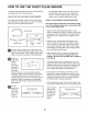
HOW TO USE THE MANUAL MODE _1 _ 1 The matrix-When the manual mode or the iFIT.com mode is selected, the matrix will show a track representing 440 revolutions (a distance of approximately 1/4 mile). As you exercise, the indicators around the track will light in succession until the entire track is lit. The track will then darken and the indicators will Press anytobutton onthe theconsole. console or begin pedaling turn on Make sure that the power cord is properly plugged in (see page 12).
r_ Note: The console can show the total number of hours When your pulse is detected, the Heart Rate indicator that the elliptical E:s TIME E:_ SEGMENT TIME RAMP _ TOTAL REVS, exerciser has been used and the total number of revolutions pedaled. To view this information, hold down the Program button for about three seconds. The left display will show the total number of hours that the elliptical exerciser has been used. Press the Start button.
series of tones will sound, and all resistance settings will move one column to the left. The resistance setting for the second segment will then be shown in the flashing Current Segment column and the resistance of the elliptical exerciser will automatically change to the resistance setting for the second segment.
D HOW TO USE HEART RATE PROGRAMS djust the angle of the ramp as desired. See step 4 on page 14. _ Heart rate program 9 is designed to keep your heart rate between 50% and 80% of your estimated maximum heart rate during your workout. (Your maximum heart rate is estimated by subtracting your age from 220. For example, if you are 30 years old, your estimated maximum heart rate is 190.) Heart rate program 10 will keep your heart rate between 50% and 85% of your estimated maximum heart rate.
If you have selected heart rate program 12, the letters "PLS" and the current target heart rate setting will flash in the left display. Press the - and + buttons repeatedly to change the target heart rate setting, if desired. The target heart rate setting can be from 70 to 170 beats per minute. D As you exercise, the Training Zone bar will help you to keep your heart rate near the current target heart rate setting. The lit indicators in the bar will show your actual pace.
HOW TO CONNECT YOUR PORTABLE STEREO HOW TO CONNECT YOUR CD PLAYER, VCR, OR COMPUTER Note: If your stereo has an RCA-type AUDIO OUT jack, see instruction A below. If your stereo has a 1/8" LINE OUT jack, see instruction B. If your stereo has only a PHONES jack, see instruction C. To use iFIT.com CDs, the elliptical exerciser must be connected to your portable CD player, portable stereo, home stereo, or computer with CD player. See pages 19 and 20 for connecting instructions. To use iFIT.
HOW TO CONNECT YOUR HOME STEREO HOW TO CONNECT YOUR COMPUTER Note: If your stereo has an unused LINE OUT jack, see instruction A below. If the LINE OUT jack is being used, see instruction B. Note: If your computer has a 1/8" LINE OUT jack, see instruction A. If your computer has only a PHONES jack, see instruction B. A. Plug one end of a 1/8" to RCA stereo audio cable (available at electronics stores) into the jack beneath the console.
HOW TO CONNECT YOUR VCR B. Plug one end of a 1/8" to RCA stereo audio cable (available at electronics stores) into the jack beneath the console. Plug the other end of the cable into an RCA Y-adapter (available at electronics stores). Next, remove the wire that is currently plugged into the AUDIO OUT jack on your VCR and plug the wire into the unused side of the Yadapter. Plug the Y-adapter into the AUDIO OUT jack on your VCR. Note: If your VCR has an unused AUDIO OUT jack, see instruction A below.
your workout. Simply follow your personal trainer's instructions. HOW TO USE IFIT.COM CD AND VIDEO PROGRAMS The program will function in almost the same way as a resistance and pace program (see step 3 on page 16). However, an electronic "chirping" sound will alert you when the resistance setting and/or the pace setting is about to change. To use iFIT.
HOW TO USE PROGRAMS DIRECTLY FROM OUR WEB SITE _ Read and follow the on-line instructions for using a program. Our Web site at www.iFIT.com allows you to play iFIT.com audio and video programs directly from the intemet. To use programs from our Web site, the elliptical exerciser must be connected to your home computer. See HOW TO CONNECT YOUR COMPUTER on page 20. In addition, you must have an intemet connection and an internet service provider.
MAINTENANCE AND TROUBLESHOOTING HOW TO MOVE THE ELLIPTICAL EXERCISER Inspect and properly tighten all parts of the elliptical exerciser regularly. Replace any worn parts immediately. Stand in front of the elliptical exerciser, hold the handlebars firmly, and place one foot against the ramp in the location shown below. Pull the handlebars until the elliptical exerciser can be moved on the front wheels, and carefully move the elliptical exerciser to the desired location.
CONDITIONING GUIDELINES During the first few minutes of exercise, your body uses easily accessible carbohydrate calories for energy. Only after the first few minutes of exercise does your body begin to use stored fat calories for energy. If your goal is to burn fat, adjust the intensity of your exercise until your heart rate is near the lowest number in your training zone as you exercise.
SUGGESTED STRETCHES The correct form for several basic stretches is shown below. Move slowly as you stretch--never 1. Toe Touch Stretch Stand with your knees bent slightly and slowly bend forward from your hips. Allow your back and shoulders to relax as you reach down toward your toes as far as possible. Hold for 15 counts, then relax. Repeat 3 times. Stretches: Hamstrings, back of knees and back. 2. Hamstring Stretch Sit with one leg extended.
NOTES 27
PART LIST--Model Key No. Qty. 1 2 3 4 5 6 7 8 9 10 11 12 13 14 15 16 17 18 19 20 21 22 23 24 25 26 27 28 29 30 31 32 33 34 35 36 37 38 39 40 41 42 43 44 45 46 47 48 49 50 51 52 53 1 1 1 1 1 1 2 1 2 1 1 1 1 1 1 1 1 2 1 2 1 1 1 1 1 2 1 2 4 2 2 1 4 1 1 1 1 1 1 1 1 1 1 2 1 2 4 2 1 1 2 1 1 No. HRE99940 Description R0204A Key No. Qty.
Key No. Qty. 107 108 109 2 1 2 110 111 112 113 114 Description Key No. Qty. Lower Foam Grip M4 x 63.5mm Tek Screw Wheel 115 116 117 4 2 Wheel Bushing M8 x 19mm Patch Screw 118 119 2 2 2 1 2 1 2 3 Left Upper Body Arm Torque Washer M10 x 25mm Button Screw # # Description M10 x 105 Carriage Bolt M4 x 58mm Screw Incline Motor Bushing Right Upper Body Arm Outer Pedal Leg Bushing Allen Wrench User's Manual Note: # indicates a non-illustrated part.
EXPLODED DRAWlNGmModel No.
98 33 21 9_ 63 65 8 _] 67 -f 98 75 ---r,'i 117 61 36 89 117 67 49 71 \ 59 \\, 72 78 \ 76 48 44 35 89 76 14 3O 64 48 38 47 76 97 92 43 47 73 51- 65 33 77 42 \ 70 89 93 ,//' c_ \ // "w 115
HOW TO ORDER REPLACEMENT PARTS To order replacement parts, simply call our Customer Service Department toll-free at 1-888-922-4222, Monday through Friday, 6 a.m. until 6 p.m. Mountain Time (excluding holidays).