www.healthrider.com Model No. HREX53009.1 Serial No. Write the serial number in the space above for reference. Serial Number Decal (under frame) QUESTIONS? If you have questions, or if parts are damaged or missing, DO NOT CONTACT THE STORE; please contact Customer Care. IMPORTANT: Please register this product (see the limited warranty on the back cover of this manual) before contacting Customer Care. 1-888-922-4222 CALL TOLL-FREE: Mon.–Fri., 6 a.m.–6 p.m. MT Sat. 8 a.m.–4 p.m. MT ON THE WEB: www.
TABLE OF CONTENTS WARNING DECAL PLACEMENT . . . . . . . . . . . . . . . . . . . . . . . . . . . . . . . . . . . . . . . . . . . . . . . . . . . . . . . . . . . . . .2 IMPORTANT PRECAUTIONS . . . . . . . . . . . . . . . . . . . . . . . . . . . . . . . . . . . . . . . . . . . . . . . . . . . . . . . . . . . . . . . .3 BEFORE YOU BEGIN . . . . . . . . . . . . . . . . . . . . . . . . . . . . . . . . . . . . . . . . . . . . . . . . . . . . . . . . . . . . . . . . . . . . . .4 ASSEMBLY . . . . . . . . . . . . .
IMPORTANT PRECAUTIONS WARNING: To reduce the risk of serious injury, read all important precautions and instructions in this manual and all warnings on your exercise bike before using your exercise bike. ICON assumes no responsibility for personal injury or property damage sustained by or through the use of this product. 1. Before beginning any exercise program, consult your physician. This is especially important for persons over age 35 or persons with pre-existing health problems. 8.
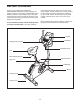
BEFORE YOU BEGIN Thank you for selecting the revolutionary HEALTHRIDER® H30X exercise bike. Cycling is an effective exercise for increasing cardiovascular fitness, building endurance, and toning the body. The H30X exercise bike provides an impressive selection of features designed to make your workouts at home more effective and enjoyable. after reading this manual, please see the front cover of this manual. To help us assist you, note the product model number and serial number before contacting us.
ASSEMBLY To hire an authorized service technician to assemble the exercise bike, call 1-800-445-2480. Assembly requires two persons. Place all parts of the exercise bike in a cleared area and remove the packing materials. Do not dispose of the packing materials until assembly is completed. In addition to the included tool(s), assembly requires a Phillips screwdriver wrench , and a rubber mallet . , an adjustable See the drawings below to identify the small parts needed for assembly.
1. 1 To make assembly easier, read the information on page 5 before you begin. Attach the Rear Stabilizer (3) to the Frame (1) with two M10 x 95mm Patch Screws (76). 3 1 76 2. Attach the Front Stabilizer (2) to the Frame (1) with two M10 x 95mm Patch Screws (76). 2 2 1 3. Loosen the Adjustment Knob (27) in the Frame (1) a few turns. 3 Orient the Seat Post (6) as shown. Then, pull the Adjustment Knob (27) outward and insert the Seat Post into the Frame (1).
4. Orient the Seat (23) and the Seat Carriage (24) as shown. 4 Attach the Seat (23) to the Seat Carriage (24) with four M8 Locknuts (72) and four M8 Split Washers (75). 23 91 Slide the Seat Carriage (24) onto the Seat Post (6). Then, slide the Seat Carriage all the way forward and tighten the Seat Adjustment Knob (26). 24 Attach an M4 x 5mm Bright Screw (91) to the rear of the Seat Post (6). 6 26 75 72 5. Apply some of the included grease to an M6 x 70mm Bolt Set (50).
6. While another person holds the Console (13) near the Handlebar (5), connect the wires on the Console to the Extension Wire (59) and to the Pulse Wire (61). 6 Avoid pinching the wires Insert the excess wire into the Handlebar (5) or into the Console (13). 13 Tip: Avoid pinching the wires. Attach the Console (13) to the Handlebar (5) with four M4 x 16mm Screws (90). 61 59 5 90 7. Orient the Upright (4) assembly and the Pivot Cover (12) as shown.
8. Slide the Front Shield Cover (7) upward onto the Upright (4). 8 While another person holds the Upright (4) near the Frame (1), connect the Extension Wire (59) to the Main Wire (58). Insert the Upright (4) into the Frame (1). Tip: Avoid pinching the wires. Attach the Upright (4) with four M8 x 20mm Patch Screws (74) and four M8 Split Washers (75). Avoid pinching the wires Slide the Front Shield Cover (7) downward to the Frame (1) and press it into place. 7 4 75 1 74 59 58 75 75 9.
. Plug the Power Adapter (67) into the receptacle on the frame of the exercise bike. To plug the Power Adapter (67) into an outlet, see HOW TO PLUG IN THE POWER ADAPTER on page 11. 10 67 11. Make sure that all parts are properly tightened before you use the exercise bike. Note: Some hardware may be left over after assembly is completed. Place a mat under the exercise bike to protect the floor or carpet.
HOW TO USE THE EXERCISE BIKE HOW TO PLUG IN THE POWER ADAPTER HOW TO ADJUST THE HEIGHT OF THE SEAT IMPORTANT: If the exercise bike has been exposed to cold temperatures, allow it to warm to room temperature before you plug in the power adapter. If you do not do this, you may damage the console displays or other electronic components. Plug the power adapter into the receptacle on the frame of the exercise bike.
HOW TO ADJUST THE ANGLE OF THE HANDLEBAR HOW TO ADJUST THE PEDAL STRAPS To adjust the pedal straps, first pull the ends of the straps off the tabs on the pedals. Then, adjust the straps to the desired position, and press the ends of the straps onto the tabs. To adjust the angle of the handlebar, first loosen the adjustment knob a few turns. Next, pull the knob outward, pivot the handlebar to the desired angle, and then release the knob into an adjustment hole.
CONSOLE DIAGRAM FEATURES OF THE CONSOLE With the iFit Live mode, you can download personalized workouts, create your own workouts, track your workout results, and access many other features. See www.iFit.com for complete information. The advanced console offers an array of features designed to make your workouts more effective and enjoyable. To purchase an iFit Live module at any time, go to www.iFit.com or call the telephone number on the front cover of this manual.
HOW TO ACTIVATE THE CONSOLE 3. Change the resistance of the pedals as desired. The included power adapter can be used to operate the exercise bike. See HOW TO PLUG IN THE POWER ADAPTER on page 11. When the power adapter is plugged in, the displays will turn on and the console will be ready for use. As you pedal, change the resistance of the pedals by pressing the Resistance increase and decrease buttons.
Time—When the manual mode is selected, this display mode will show the elapsed time. When a workout is selected, this display mode will show the time remaining in the workout instead of the elapsed time. HOW TO USE A PRESET WORKOUT 1. Begin pedaling or press any button on the console to turn on the console. See HOW TO ACTIVATE THE CONSOLE on page 14. Watts—This display will show your power output in watts. 2. Select a preset workout.
IMPORTANT: The target speed is intended only to provide motivation. Your actual pedaling pace may be slower than the target speed. Make sure to pedal at a pace that is comfortable for you. 3. Begin pedaling to start the workout. Each workout is divided into one-minute segments. One resistance level and one target speed are programmed for each segment. Note: The same resistance level and/or target speed may be programmed for consecutive segments.
HOW TO USE THE INFORMATION MODE HOW TO USE THE IFIT TRAINING MODE The console features an information mode that allows you to view usage information for the exercise bike, select a unit of measurement for the console, and adjust the contrast level of the display. The optional iFit Live module allows your console to communicate with your wireless network and unlocks exciting new features.
4. Adjust the contrast level of the display if desired. 7. Check the status of the iFit Live module if desired. The currently selected contrast level will also appear in the display. To change the contrast level, press the increase and decrease buttons until the bullet appears next to the word CONTRAST. To check the status of the iFit Live module, press the increase and decrease buttons until the bullet appears next to the words CHECK WIFI STATUS or CHECK USB STATUS.
MAINTENANCE AND TROUBLESHOOTING Inspect and tighten all parts of the exercise bike regularly. Replace any worn parts immediately. Next, rotate the Left Crank Arm (20) to a vertical position with the end of the Left Crank Arm pointing upward. To clean the exercise bike, use a damp cloth and a small amount of mild soap. IMPORTANT: To avoid damage to the console, keep liquids away from the console and keep the console out of direct sunlight.
HOW TO ADJUST THE DRIVE BELT Next, rotate the Right Crank Arm (19) to a vertical position with the end of the Right Crank Arm pointing upward. If you can feel the pedals slip while you are pedaling, even when the resistance is adjusted to the highest level, the drive belt may need to be adjusted. Rotate the right Pedal Disc (17) clockwise to release it from the Right Shield (10). Then, work the right Pedal Disc upward and remove it from the Right Crank Arm (19).
EXERCISE GUIDELINES WARNING: Burning Fat—To burn fat effectively, you must exercise at a low intensity level for a sustained period of time. During the first few minutes of exercise, your body uses carbohydrate calories for energy. Only after the first few minutes of exercise does your body begin to use stored fat calories for energy. If your goal is to burn fat, adjust the intensity of your exercise until your heart rate is near the lowest number in your training zone.
PART LIST Key No. Qty. 1 2 3 4 5 6 7 8 9 10 11 12 13 14 15 16 17 18 19 20 21 22 23 24 25 26 27 28 29 30 31 32 33 34 35 36 37 38 39 40 41 42 43 44 45 46 47 48 49 50 1 1 1 1 1 1 1 1 1 1 1 1 1 1 1 1 2 2 1 1 1 1 1 1 2 1 2 1 2 1 2 2 1 1 2 2 2 1 1 2 2 1 2 1 1 1 1 1 1 1 Description Key No. Qty.
EXPLODED DRAWING 23 65 91 24 75 26 72 89 9 68 31 61 62 10 70 32 40 73 86 29 89 76 28 27 41 45 3 89 89 59 89 42 66 69 50 90 60 88 79 77 32 89 31 27 74 75 57 74 41 60 84 85 72 83 47 96 52 97 78 72 75 46 43 48 49 81 82 5 51 75 50 64 94 90 76 2 36 89 89 33 58 55 95 67 38 89 54 35 89 36 71 55 87 94 43 90 12 39 80 97 23 74 1 63 40 56 75 37 92 35 34 7 74 90 53 4 90 66 90 51 89 44 37 14 93 62 20 18 73 29 93 93 8
ORDERING REPLACEMENT PARTS To order replacement parts, please see the front cover of this manual.