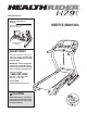
www.healthrider.com Model No. HRTL80510.0 Serial No. Write the serial number in the space above for reference. Serial Number Decal QUESTIONS? If you have questions, or if parts are damaged or missing, DO NOT CONTACT THE STORE; please contact Customer Care. IMPORTANT: Please register this product (see the limited warranty on the back cover of this manual) before contacting Customer Care. 1-888-922-4222 CALL TOLL-FREE: Mon.–Fri. 6 a.m.–6 p.m. MT Sat. 8 a.m.–4 p.m. MT ON THE WEB: www.healthriderservice.
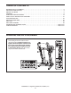
TABLE OF CONTENTS WARNING DECAL PLACEMENT . . . . . . . . . . . . . . . . . . . . . . . . . . . . . . . . . . . . . . . . . . . . . . . . . . . . . . . . . . . . . .2 IMPORTANT PRECAUTIONS . . . . . . . . . . . . . . . . . . . . . . . . . . . . . . . . . . . . . . . . . . . . . . . . . . . . . . . . . . . . . . . .3 BEFORE YOU BEGIN . . . . . . . . . . . . . . . . . . . . . . . . . . . . . . . . . . . . . . . . . . . . . . . . . . . . . . . . . . . . . . . . . . . . . .5 ASSEMBLY . . . . . . . . . . . . .
IMPORTANT PRECAUTIONS WARNING: To reduce the risk of serious injury, read all important precautions and instructions in this manual and all warnings on your treadmill before using your treadmill. ICON assumes no responsibility for personal injury or property damage sustained by or through the use of this product. 1. Before beginning any exercise program, consult your physician. This is especially important for persons over age 35 or persons with pre-existing health problems. carrying 15 or more amps.
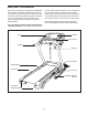
24. Inspect and properly tighten all parts of the treadmill regularly. 20. Never leave the treadmill unattended while it is running. Always remove the key, unplug the power cord, and press the power switch into the off position when the treadmill is not in use. (See the drawing on page 5 for the location of the power switch.) 25. 21. Do not attempt to raise, lower, or move the treadmill until it is properly assembled. (See ASSEMBLY on page 6, and HOW TO FOLD AND MOVE THE TREADMILL on page 21.
BEFORE YOU BEGIN Thank you for selecting the revolutionary HealthRider® H79T treadmill. The H79T treadmill offers an impressive selection of features designed to make your workouts at home more enjoyable and effective. And when youʼre not exercising, the unique treadmill can be folded up, requiring less than half the floor space of other treadmills. ing this manual, please see the front cover of this manual.
ASSEMBLY To hire an authorized service technician to assemble the treadmill, call 1-800-445-2480. Assembly requires two persons. Set the treadmill in a cleared area and remove all packing materials. Do not dispose of the packing materials until assembly is completed. Note: The underside of the treadmill walking belt is coated with high-performance lubricant. During shipping, some lubricant may be transferred to the top of the walking belt or the shipping carton.
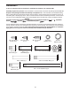
1. Make sure that the power cord is unplugged. Place a piece of cardboard below the rear of the Frame (57) to protect the floor or carpet. 1 Attach the Left Wheel Cap (92) to the Base (91) with two #8 x 3/4" Screws (2). Attach the Right Wheel Cap (not shown) to the right side of the Base (91) in the same way. 91 2. Pull the Upright Wire (77) and the Ground Wire (90) through the indicated hole in the Base (91).
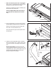
4. Hold the Left Upright (88) against the Base (91). Be careful not to pinch the Upright Wire (77) or the Ground Wire (90). Insert two 3/8" x 2 3/4" Patch Bolts (7) and two 3/8" x 1 1/4" Patch Bolts (8) with two 3/8" Star Washers (13) into the Left Upright. 4 88 Partially tighten the 3/8" x 2 3/4" Patch Bolts (7) and the 3/8" x 1 1/4" Patch Bolts (8) until the heads of the Patch Bolts touch the Left Upright (88); do not fully tighten the Patch Bolts yet.
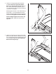
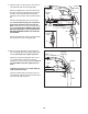
6. Identify the Left Handrail (81) and the Right Handrail (82). Attach the Handrails to the Pulse Bar Bottom (87) with four 3/8" x 3/4" Patch Bolts (9). Start all four Patch Bolts, and then tighten each of them. 6 9 87 9 81 7. Hold the Pulse Bar Top (86) near the Pulse Bar Bottom (87). Insert the pulse wire from the Pulse Bar Top into the Left Handrail (81) and out of the large hole in the Pulse Bar Bottom.
9. With the help of a second person, hold the console assembly near the Left Upright (88). Route the Upright Wire (77) and the pulse wire from the Left Upright (88) around the indicated crossbar. Then, route the wires through the looped ties on the bottom of the console assembly. 9 Console Wire Connect the Upright Wire (77) to the console wire. See the inset drawing. The connectors should slide together easily and snap into place. If they do not, turn one connector and try again.
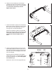
. Attach the Left Tray (104) and the Right Tray (105) to the console assembly with six #8 x 1/2" Screws (1). 11 104 105 1 12. Firmly tighten the four 3/8" x 2 3/4" Patch Bolts (7) and the four 3/8" x 1 1/4" Patch Bolts (8) (only one side is shown). 12 1 84 Press the Left Base Cover (83) and the Right Base Cover (84) onto the Base (91) until they snap into place. 83 7 8 13. Make sure that there is a piece of cardboard below the rear of the Frame (57).
14. IMPORTANT: Before you begin this step, make sure that you have read and followed all the instructions in step 13. 14 57 Raise the Frame (57) to the position shown. Have a second person hold the Frame until this step is completed. 12 Orient the Storage Latch (58) so that the large barrel and the latch knob are oriented as shown. Attach the upper end of the Storage Latch (58) to the bracket on the Frame (57) with a 3/8" x 1 3/4" Patch Bolt (6) and a 3/8" Nut (12).
OPERATION AND ADJUSTMENT THE PRE-LUBRICATED WALKING BELT Your treadmill features a walking belt coated with highperformance lubricant. IMPORTANT: Never apply silicone spray or other substances to the walking belt or the walking platform. Such substances will cause excessive wear. HOW TO PLUG IN THE POWER CORD DANGER: Improper connection that is properly installed and grounded in accordance with all local codes and ordinances. IMPORTANT: The treadmill is not compatible with GFCI-equipped outlets.
CONSOLE DIAGRAM FEATURES OF THE CONSOLE The treadmill console offers an impressive array of features designed to make your workouts more effective and enjoyable. When you use the manual mode, you can change the speed and incline of the treadmill with the touch of a button. As you exercise, the console will display instant exercise feedback. You can even measure your heart rate using the handgrip pulse sensor.
HOW TO TURN ON THE POWER IMPORTANT: If the treadmill has been exposed to cold temperatures, allow it to warm to room temperature before turning on the power. If you do not do this, you may damage the console displays or other electrical components. Plug in the power cord (see page 13). Next, locate the power switch on the treadmill frame near the power cord. Press the power switch into the reset position. 2. Select the manual mode. Press the Manual button on the console.
5. Follow your progress with the displays. Press the Home button to return to the default menu (see THE INFORMATION MODE on page 19 to set the default menu). If necessary, press the Home button again. As you walk or run on the treadmill, the display can show the following workout information: • The elapsed time When a wireless iFit Live module is connected, the wireless symbol at the top of the display will show the strength of your wireless signal. Four arcs indicate full signal strength.
HOW TO USE AN ONBOARD WORKOUT programmed for the next segment, the new speed and/or incline settings will appear in the display for a few seconds and the treadmill will automatically adjust to the new speed and/or incline setting. Note: During some workouts, the next segment of the profile will not flash in the display. 1. Insert the key into the console. See HOW TO TURN ON THE POWER on page 15. 2. Select an onboard workout.
HOW TO USE AN IFIT LIVE WORKOUT Note: To use an iFit Live workout, you must have an optional iFit Live module. To purchase an iFit Live module at any time, go to www.iFit.com or call the telephone number on the front cover of this manual. You must also have access to a computer with a USB port and an internet connection. In addition, you must have access to a wireless network including an 802.11b router with SSID broadcast enabled (hidden networks are not supported). An iFit.
THE COOL DOWN MODE To select the cool down mode, press the Cool Down button. Then, press the Start button. The walking belt will begin to move at 2.5 mph. After a few minutes, the walking belt will slow to a stop. THE INFORMATION MODE The console features an information mode that keeps track of treadmill information and allows you to personalize console settings. To select the information mode, hold down the Stop button while inserting the key into the console and then release the Stop button.
HOW TO USE THE STEREO SOUND SYSTEM HOW TO ADJUST THE CUSHIONING SYSTEM Remove the key from the console and unplug the power cord. The treadmill features a cushioning system that reduces the impact as you walk or run on the treadmill. To increase the firmness of the walking platform, step off the treadmill and slide the platform cushions toward the front of the treadmill. To decrease the firmness, step off the treadmill and slide the platform cushions toward the back of the treadmill.
HOW TO FOLD AND MOVE THE TREADMILL HOW TO FOLD THE TREADMILL HOW TO MOVE THE TREADMILL To avoid damaging the treadmill, adjust the incline to the lowest position before you fold the treadmill. Then, remove the key and unplug the power cord. CAUTION: You must be able to safely lift 45 lbs. (20 kg) to raise, lower, or move the treadmill. Before moving the treadmill, fold it as described at the left. CAUTION: Make sure that the latch knob is locked in the storage position.
TROUBLESHOOTING Most treadmill problems can be solved by following the simple steps below. Find the symptom that applies, and follow the steps listed. If further assistance is needed, see the front cover of this manual. PROBLEM: The power does not turn on SOLUTION: a. Make sure that the power cord is plugged into a surge suppressor, and that the surge suppressor is plugged into a properly grounded outlet (see page 13).
Locate the Reed Switch (55) and the Magnet (54) on the left side of the Pulley (53). Turn the Pulley until the Magnet is aligned with the Reed Switch. Make sure that the gap between the Magnet and the Reed Switch is about 1/8 in. (3 mm). If necessary, loosen the #8 x 3/4" Tek Screw (14), move the Reed Switch slightly, and then retighten the Screw. Reattach the Motor Hood (not shown) and run the treadmill for a few minutes to check for a correct speed reading. 14 55 1/8 in.
PROBLEM: The walking belt is off-center or slips when walked on SOLUTION: a. If the walking belt is off-center, first remove the key and UNPLUG THE POWER CORD. If the walking belt has shifted to the left, use the hex key to turn the left idler roller bolt clockwise 1/2 of a turn; if the walking belt has shifted to the right, turn the left idler roller bolt counterclockwise 1/2 of a turn. Be careful not to overtighten the walking belt.
EXERCISE GUIDELINES WARNING: Before beginning this Burning Fat—To burn fat effectively, you must exercise at a low intensity level for a sustained period of time. During the first few minutes of exercise, your body uses carbohydrate calories for energy. Only after the first few minutes of exercise does your body begin to use stored fat calories for energy. If your goal is to burn fat, adjust the intensity of your exercise until your heart rate is near the lowest number in your training zone.
PART LIST—Model No. HRTL80510.0 To locate the parts listed below, see the EXPLODED DRAWING near the end of this manual. Key No. Qty. 1 2 3 4 5 6 7 8 9 10 11 12 13 14 15 16 17 18 19 20 21 22 23 24 25 26 27 28 29 30 31 32 33 34 35 36 37 38 39 40 41 42 43 44 45 46 47 48 49 50 26 58 1 4 4 1 4 4 4 7 4 2 8 1 2 2 2 1 2 4 12 2 2 2 2 2 4 1 8 1 8 4 2 6 4 5 4 2 2 2 1 2 1 1 1 1 1 1 2 1 Description Key No. Qty.
Key No. Qty. 101 102 103 104 4 1 1 1 Description Key No. Qty. Console Clamp Frame Ground Wire Console Base Left Tray 105 106 * 1 2 – Description Right Tray Cable Tie Userʼs Manual Note: Specifications are subject to change without notice. For information about ordering replacement parts, see the back cover of this manual. *These parts are not illustrated.
41 15 28 2 42 2 1 63 2 62 64 43 22 27 31 1 40 2 37 32 35 46 44 39 38 15 31 2 2 45 21 2 47 21 35 32 1 42 27 48 31 2 2 37 20 12 22 40 31 49 1 21 1 1 31 50 2 21 37 32 35 25 27 6 61 21 52 14 31 2 39 54 53 21 60 23 19 55 20 38 58 10 49 23 24 12 27 59 51 37 32 35 1 28 30 56 57 25 10 3 19 EXPLODED DRAWING A—Model No. HRTL80510.
EXPLODED DRAWING B—Model No. HRTL80510.
EXPLODED DRAWING C—Model No. HRTL80510.
EXPLODED DRAWING D—Model No. HRTL80510.
ORDERING REPLACEMENT PARTS To order replacement parts, please see the front cover of this manual.