
Owner's Manual

10
Console
Assembly
Pulse
Wires
Ties
88
9
77
7
7
Console
Wire
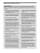
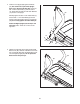
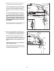
10. Set the console assembly on the brackets on
the Left Upright (88) and the Right Upright (not
shown). Be careful not to pinch any wires.
Attach the console assembly with four 5/16" x
1 1/4" Patch Bolts (4) and four 5/16" Star
Washers (11) (only one side is shown). Start all
four Patch Bolts, and then tighten each of
them.
Tighten the four 3/8" x 4 1/2" Patch Bolts (5)
(only one side is shown).
Insert the excess wires into the hole in the con-
sole assembly. Tighten the ties around the wires
and cut off the ends of the ties.
10
Console
Assembly
11
4
88
5
Bracket
Console
Wire
Ties
Hole
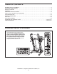
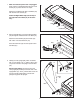
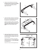
9. With the help of a second person, hold the con-
sole assembly near the Left Upright (88).
R
oute the Upright Wire (77) and the pulse wire
from the Left Upright (88) around the indicated
c
rossbar. Then, route the wires through the
looped ties on the bottom of the console assem-
bly.
Connect the Upright Wire (77) to the console
wire. See the inset drawing. The connectors
should slide together easily and snap into
place. If they do not, turn one connector and try
again. IF YOU DO NOT CONNECT THE CON-
NECTORS PROPERLY, THE CONSOLE MAY
BECOME DAMAGED WHEN YOU TURN ON
THE POWER.
Connect the pulse wire in the console assembly
to the pulse wire in the Left Upright (88).
Crossbar