Owner’s Manual Installation and Operation Models: 6000GBV 6000GBV-IPI 6000GBV-LP 6000GBV-IPILP NOTICE DO NOT DISCARD THIS MANUAL • Important operating and maintenance instructions included. • Read, understand and follow these instructions for safe installation and operation. WARNING: If the information in these instructions is not followed exactly, a fire or explosion may result causing property damage, personal injury, or death.
Read this manual before installing or operating this appliance. Please retain this owner’s manual for future reference. A. Congratulations This owner’s manual should be retained for future reference. We suggest that you keep it with your other important documents and product manuals. Congratulations on selecting a Heat & Glo gas fireplace, an elegant and clean alternative to wood burning fireplaces.
Safety Alert Key: • • • • DANGER! Indicates a hazardous situation which, if not avoided will result in death or serious injury. WARNING! Indicates a hazardous situation which, if not avoided could result in death or serious injury. CAUTION! Indicates a hazardous situation which, if not avoided, could result in minor or moderate injury. NOTICE: Used to address practices not related to personal injury. Table of Contents A. Congratulations . . . . . . . . . . . . . . . . . . . . . . . . . . . . . . . . .
13 Finishing A. Mantel and Wall Projections . . . . . . . . . . . . . . . . . . . . . . . 32 B. Facing Material . . . . . . . . . . . . . . . . . . . . . . . . . . . . . . . . . 32 14 Appliance Setup A. B. C. D. E. F. G. H. I. Remove Glass Assembly . . . . . . . . . . . . . . . . . . . . . . . . . Remove the Shipping Materials . . . . . . . . . . . . . . . . . . . . Clean the Appliance . . . . . . . . . . . . . . . . . . . . . . . . . . . . . Accessories . . . . . . . . . . . . . . . . . . . . . . . . . .
B. Limited Lifetime Warranty Hearth & Home Technologies LIMITED WARRANTY Hearth & Home Technologies (“HHT”) and its respective brands extends the following warranty for HHT gas, wood, pellet and electric appliances purchased from an authorized HHT dealer and installed in the United States of America or Canada. Warranty starts with date of purchase by the original owner (End User) except as noted for replacement parts.
B. Limited Lifetime Warranty (continued) • This limited warranty does not extend to or include surface finish on the appliance or terminations, door gasketing, glass gasketing, glass discoloration, firebrick, pellet logs, kaowool or other ceramic insulating materials. Rust and/or corrosion on any of the metal surfaces, cast iron components, baffles, firepots, doors, or firebox area are not covered by this warranty.
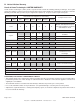
1 Listing and Code Approvals A. Appliance Certification MODELS: 6000GBV, 6000GBV-IPI, 6000GBV-LP, 6000GBV-IPILP LABORATORY: Underwriters Laboratories, Inc. (UL) TYPE: B-Vent Gas Appliance C. BTU Specifications Models U.S. (0-2000 ft.) or Canada (2000-4500 ft.) 6000GBV 6000GBV-IPI This product is listed to ANSI standards for “Vented Gas Fireplaces” and “Gas Fired Appliances for Use at High Altitudes”.
2 Operating Instructions User Guide • Keep remote controls out of reach of children. A. Gas Fireplace Safety • Never leave children alone near a hot fireplace, whether operating or cooling down. WARNING HOT SURFACES! Glass and other surfaces are hot during operation AND cool down. Hot glass will cause burns. • DO NOT touch glass until it is cooled • NEVER allow children to touch glass • Keep children away • CAREFULLY SUPERVISE children in same room as fireplace.
C. Fan Kit (optional) For safety: If desired, a fan kit may be added. Contact your dealer to order the correct fan kit. • Install a switch lock or a wall/remote control with child protection lockout feature. D. Clear Space • Keep remote controls out of reach of children. WARNING! DO NOT place combustible objects in front of the fireplace or block louvers. High temperatures may start a fire. See Figure 2.2. See your dealer if you have questions.
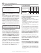
J. Lighting Instructions (IPI) The IPI system may be operated with two D-cell batteries. When using batteries, unplug the transformer. To prolong battery life, remove them when using the transformer. FOR YOUR SAFETY READ BEFORE LIGHTING WARNING: If you do not follow these instructions exactly, a fire or explosion may result causing property damage, personal injury or loss of life. A. This appliance is equipped with an intermittent pilot ignition (IPI) device which automatically lights the burner.
K. Lighting Instructions (Standing Pilot) FOR YOUR SAFETY READ BEFORE LIGHTING LIGHTING INSTRUCTIONS 1. Open control access panel. WARNING: If you do not follow these instructions exactly, a fire or explosion may result causing property damage, personal injury or loss of life. A. This appliance has a pilot which must be lighted by hand. When lighting the pilot, follow these instructions exactly. B. BEFORE LIGHTING, smell all around the appliance area for gas.
L. After Fireplace is Lit Initial Break-in Procedure • The fireplace should be run three to four hours continuously on high. • Turn the fireplace off and allow it to completely cool. • Remove fixed glass assembly. See Section 14.G. • Clean fixed glass assembly. See Section 3. • Replace the fixed glass assembly and run continuously on high an additional 12 hours. This cures the materials used to manufacture the fireplace. NOTICE! Open windows for air circulation during fireplace break-in.
3 Maintenance and Service Any safety screen or guard removed for servicing must be replaced prior to operating the fireplace. Doors, Surrounds, Fronts Frequency: Annually When properly maintained, your fireplace will give you many years of trouble-free service. We recommend annual service by a qualified service technician. By: Homeowner A. Maintenance Tasks-Homeowner • Inspect for scratches, dents or other damage and repair as necessary.
Venting Frequency: Annually Frequency: Seasonally By: Qualified Service Technician By: Homeowner Tools needed: Protective gloves, vacuum cleaner, dust cloths Tools needed: Protective gloves and safety glasses. • Inspect venting and termination cap for blockage or obstruction such plants, bird nests, leaves, snow, debris, etc. • Vacuum and wipe out dust, cobwebs, debris or pet hair. Use caution when cleaning these areas. Screw tips that have penetrated the sheet metal are sharp and should be avoided.
Figure 3.1 IPI Pilot Flame Patterns Figure 3.2 Standing Pilot Flame Patterns Heat & Glo • 6000GBV, 6000GBV-IPI • 2104-900 Rev.
4 Installer Guide Getting Started A. Typical Appliance System NOTICE: Illustrations and photos reflect typical installations and are for design purposes only. Illustrations/diagrams are not drawn to scale. Actual product may vary from pictures in manual VERTICAL TERMINATION CAP (SECTION 6) NON-COMBUSTIBLE ROOF FLASHING MAINTAINS MINIMUM CLEARANCE AROUND PIPE (SECTION 4.D) STORM COLLAR (SECTION 4.D) VENT PIPE PENETRATES ROOF PREFERABLY WITHOUT AFFECTING ROOF RAFTERS (SECTION 8.
B. Design and Installation Considerations Heat & Glo B-type vent gas appliances are designed to operate with all exhaust gases expelled to the outside of the building, and combustion air pulled from the room. • The vent system components and decorative doors and fronts may be shipped in separate packages. • If packaged separately, the log set and appliance grate must be installed. Installation MUST comply with local, regional, state and national codes and regulations.
E. Negative Pressure WARNING! Asphyxiation Risk! Negative pressure can cause spillage of combustion fumes and soot. Fireplace needs to draft properly for safety. Draft is the pressure difference needed to vent fireplaces successfully. Considerations for successful draft include: • Preventing negative pressure • Location of fireplace and chimney Negative pressure results from the imbalance of air available for the fireplace to operate properly.
5 Framing and Clearances NOTICE: Illustrations reflect typical installations and are FOR DESIGN PURPOSES ONLY. Illustrations/diagrams are not drawn to scale. Actual installation may vary due to individual design preference. A. Selecting Appliance Location When selecting a location for the appliance it is important to consider the required clearances to walls (see Figure 5.1). WARNING! Risk of Fire or Burns! Provide adequate clearance around air openings and for service access.
To further prevent drafts, the wall shield and ceiling firestops should be caulked with high temperature caulk to seal gaps. Gas line holes and other openings should be caulked with high temp caulk or stuffed with unfaced insulation. If the appliance is being installed on a cement slab, a layer of plywood may be placed underneath to prevent conducting cold up into the room. B.
Combustible Mantel Legs or Wall Projections D. Mantel and Wall Projections WARNING! Risk of Fire! Comply with all minimum clearances as specified. Framing or finishing material closer than the minimums listed must be constructed entirely of noncombustible materials (i.e., steel studs, concrete board, etc). INTERIOR WALL TOP VIEW Combustible Mantels A B TO CEILING 18 FIREPLACE OPENING 12 Note: All measurements in inches.
6 Termination Locations A. Vent Termination Minimum Clearances B-VENT GAS, WOOD OR FUEL OIL TERMINATION B WARNING Fire Risk. Maintain vent clearance to combustibles as specified. • DO NOT pack air space with insulation or other materials. Failure to keep insulation or other materials away from vent pipe may cause overheating and fire. 8 FEET LISTED B-VENT TERMINATION CAP C A GAS TERMINATION VERTICAL WALL LOWEST DISCHARGE OPENING Wood & Fuel Oil Gas Termination Termination A 6 in. 20 in. min.
7 Vent Information and Diagrams A. Vent Guidelines WARNING! Fire Risk/Asphyxiation! This appliance requires the specified pipe for operation. Incorrect pipe may cause spillage, condensation and overheating. MINIMUM CLEARANCES ARE PER VENT MANUFACTURER’S SPECIFICATIONS These models require the following size B-vent double wall, or single wall rigid or flex vent pipe.
8 Vent Clearances and Framing A. Pipe Clearances to Combustibles B. Wall and Ceiling Penetration Framing Vent clearances are per vent manufacturer’s specifications. MUST be Listed B-Vent pipe. For a wall or ceiling penetration consult B-vent pipe manufacturer’s instructions to provide adequate clearances. Use same size framing materials as those used in the wall or ceiling construction.
9 Appliance Preparation A. Installing Outside Air Kit Damper Assembly CAUTION! Risk of Cuts/Abrasions/Flying Debris. Wear protective gloves and safety glasses during installation. Sheet metal edges are sharp. WARNING! Risk of Fire/Asphyxiation. DO NOT draw outside combustion air from: • Wall, floor or ceiling cavity. • Enclosed space such as an attic or garage. • Close proximity to exhaust vents or chimneys. Fumes or odor may result. • Remove and discard cover plate or knockout from side of appliance.
D. Securing and Leveling the Appliance WARNING! Risk of Fire! Prevent contact with: • Sagging or loose insulation • Insulation backing or plastic • Framing and other combustible materials Block openings into the chase to prevent entry of blownin insulation. Make sure insulation and other materials are secured. DO NOT notch the framing around the appliance standoffs. Failure to maintain air space clearance may cause overheating and fire.
10 Installing Vent Pipe A. Assembly of Vent Sections C. Securing Vent Sections This B-Vent appliance requires 6 inch B-vent double-wall pipe. Follow the pipe manufacturer’s installation guidelines when installing the unit. This will ensure proper operation and prevent safety hazards. Secure vent sections with vent supports following B-vent manufacturer’s instructions. WARNING! Risk of Fire/Exhaust Fumes! Assemble pipe sections per B-vent manufacturer’s instructions. Use support tabs for screws.
11 Gas Information A. Fuel Conversion C. Gas Connection • Make sure the appliance is compatible with available gas types. • Refer to Reference Section 16 for location of gas line access in appliance. • Conversions must be made by a qualified service technician using Hearth & Home Technologies specified and approved parts. • Gas line may be run through knockout(s) provided. B. Gas Pressure • Optimum appliance performance requires proper input pressures.
12 Electrical Information A. Wiring Requirements B. Standing Pilot Ignition System Wiring NOTICE: This appliance must be electrically wired and grounded in accordance with local codes or, in the absence of local codes, with National Electric Code ANSI/NFPA 70-latest edition or the Canadian Electric Code CSA C22.1. • The standing pilot ignition system wiring does not require a 110 VAC supply to operate. • Wire the appliance junction box to 110-120 VAC.
INTERMITTENT PILOT IGNITOR INTERMITTENT PILOT IGNITOR I IGNITION MODULE 3 VAC REMOTE RECEIVER S IGNITION MODULE 3 VAC WHITE TRANSFORMER 3V ORG TRANSFORMER 3 VAC WHITE GREEN ORG PLUG-IN JUMPER W IRE TO BROWN BATTERY PACK TEMP SENSOR GROUND TO FIREPLACE CHASSIS K AC BL D RE VALVE BATTERY PACK GREEN BR ORG OW N D RE BRO K AC BL ORG WN PLUG-IN GROUND TO FIREPLACE CHASSIS TEMP SENSOR THERMOSTAT WIRE ASSEMBLY VALVE Figure 12.2 Intellifire Pilot Ignition (IPI) Wiring Diagram E.
F. Junction Box Installation If the box is being wired from the INSIDE of the appliance: Romex Connector • Remove the screw attaching the junction box/receptacle to the outer shell, rotate the junction box inward to disengage it from the outer shell (see Figure 12.4). 14/2WG • Pull the electrical wires from outside the appliance through the opening into the valve compartment and secure wires with a Romex connector. See Figure 12.4.
13 Finishing A. Mantel and Wall Projections B. Facing Material WARNING! Risk of Fire! Comply with all minimum clearances as specified. Framing closer than the minimums listed must be constructed entirely of noncombustible materials (i.e., steel studs, concrete board, etc.) Failure to comply could cause fire. • Metal front faces may be covered with non-combustible materials only. Combustible Mantels • Facing and/or finishing materials must never overhang into the glass opening.
14 Appliance Setup A. Remove Glass Assembly E. Ember Placement See Section 14.G. WARNING! Risk of Explosion! Follow ember placement instructions in manual. DO NOT place embers directly over burner ports. Replace ember material annually. Improperly placed embers interfere with proper burner operation. B. Remove the Shipping Materials Remove shipping materials from inside or underneath the firebox. C.
F. Install the Log Assembly Log Assembly: LOGS-6000G If the gas logs have been factory installed they should not need to be positioned. If the logs have been packaged separately, refer to the following instructions. 1 STEP 1. CAUTION: Logs are fragile! Carefully remove the logs, grate and supporting cardboard from the inside of the fireplace See Figure 14.2. 3 4 2 5 STEP 2. Place the metal grate on top of the burner.
2 2 Figure 14.6 Front View Figure 14.7 Top View STEP 4. Log #2 (SRV2103-108): Place log #2 on top of the left side of log #1. The bottom of this log has a slot in it that goes over the tab molded into the top of log #1. The left end sits behind the simulated ember cluster on the burner top. 3 3 Figure 14.8 Front View Figure 14.9 Top View STEP 5. Log #3 (SRV2103-110): Place log #3 on top of the burner surface in front of the hump. The bottom of the log has a square groove cut through it.
G. Fixed Glass Assembly I. Air Shutter Setting WARNING! Risk of Asphyxiation! Handle fixed glass assembly with care. Inspect the gasket to ensure it is undamaged and inspect the glass for cracks, chips or scratches. Air shutter settings should be adjusted by a qualified service technician at the time of installation. The air shutter is set at the factory for minimum vertical vent run. Adjust air shutter for longer vertical runs. • DO NOT strike, slam or scratch glass.
15 Troubleshooting With proper installation, operation, and maintenance your gas appliance will provide years of trouble-free service. If you do experience a problem, this troubleshooting guide will assist a qualified service technician in the diagnosis of a problem and the corrective action to be taken. This troubleshooting guide can only be used by a qualified service technician. Contact your dealer to arrange a service call by a qualified service technician. A.
Troubleshooting (continued) Symptom 3. (Continued) Possible Cause Corrective Action C. Back drafting may be tripping the spill switch. Negative pressure, wind or flue blockage may be causing spillage. Perform negative pressure diagnostics and inspect venting. D. Valve. Turn the valve knob to the ON position. Place the ON/ OFF switch in the ON position. Take a reading with a millivolt meter at the thermopile terminals. The millivolt meter should read greater than 125mV.
B. Intellifire Ignition System Symptom Possible Cause 1. Pilot won’t light. A. Incorrect wiring. The ignitor/module makes noise, but no B. Loose connections or electrical spark. shorts in the wiring. 2. Pilot won’t light, there is no noise or spark. 3. Pilot sparks, but Pilot will not light. Corrective Action Verify “S” wire (white) for sensor and “I” wire (orange) for ignitor are connected to correct terminals on module and pilot assembly.
Intellifire Ignition System - (continued) Symptom 4. Pilot lights but continues to spark, and main burner will not ignite. (If the pilot continues to spark after the pilot flame has been lit, flame rectification has not occurred.) 40 Possible Cause A. A shorted or loose connection in flame sensing rod. Corrective Action Verify all connections to wiring diagram in manual. Verify connections underneath pilot assembly are tight.
16 Reference Materials A. Appliance Dimension Diagram Dimensions are actual appliance dimensions. Use for reference only. For framing dimensions and clearances refer to Section 5.
B. Service Parts 6000GBV Service Parts Diagram Beginning Manufacturing Date: May 2006 Ending Manufacturing Date: ______ 6 8 10 7 9 11 Log Set Assembly 1 2 4 3 5 Part number list on following page. 42 Heat & Glo • 6000GBV, 6000GBV-IPI • 2104-900 Rev.
Service Parts List 6000GBV IMPORTANT: THIS IS DATED INFORMATION. When requesting service or replacement parts for your appliance please provide model number and serial number. All parts listed in this manual may be ordered from an authorized dealer.
6000GBV-IPI Service Parts Beginning Manufacturing Date: May 2006 Ending Manufacturing Date: ______ Valve Assembly Diagram/ Parts List 1 Intermittent Pilot Ignition Valve Assembly 2 3 5 4 9 10 6 8 7 IMPORTANT: THIS IS DATED INFORMATION. When requesting service or replacement parts for your appliance please provide model number and serial number. All parts listed in this manual may be ordered from an authorized dealer.
6000GBV Service Parts Valve Assembly Diagram/ Parts List Beginning Manufacturing Date: May 2006 Ending Manufacturing Date: ______ 1 2 Standing Pilot Ignition Valve Assembly 3 5 4 6 9 7 8 IMPORTANT: THIS IS DATED INFORMATION. When requesting service or replacement parts for your appliance please provide model number and serial number. All parts listed in this manual may be ordered from an authorized dealer.
C. Contact Information Heat & Glo, a brand of Hearth & Home Technologies Inc. 7571 215th St, Lakeville, MN 55044 www.heatnglo.com Please contact your Heat & Glo dealer with any questions or concerns. For the location of your nearest Heat & Glo dealer, please visit www.heatnglo.com.