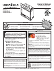
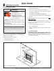
Owner’s Manual Installation and Operation Models: 6000GCF-IPI 6000GCF-IPILP NOTICE DO NOT DISCARD THIS MANUAL • Important operating and maintenance instructions included. • Read, understand and follow these instructions for safe installation and operation. WARNING: If the information in these instructions is not followed exactly, a fire or explosion may result causing property damage, personal injury, or death.
Read this manual before installing or operating this appliance. Please retain this owner’s manual for future reference. A. Congratulations This owner’s manual should be retained for future reference. We suggest that you keep it with your other important documents and product manuals. Congratulations on selecting a Heat & Glo gas fireplace, an elegant and clean alternative to wood burning fireplaces.
Safety Alert Key: • • • • DANGER! Indicates a hazardous situation which, if not avoided will result in death or serious injury. WARNING! Indicates a hazardous situation which, if not avoided could result in death or serious injury. CAUTION! Indicates a hazardous situation which, if not avoided, could result in minor or moderate injury. NOTICE: Used to address practices not related to personal injury. Table of Contents A. Congratulations . . . . . . . . . . . . . . . . . . . . . . . . . . . . . . . . .
13 Finishing A. Mantel and Wall Projections . . . . . . . . . . . . . . . . . . . . . . . 45 B. Facing Material . . . . . . . . . . . . . . . . . . . . . . . . . . . . . . . . . 45 14 Appliance Setup A. B. C. D. E. F. G. H. I. J. K. L. M. Remove Fixed Glass Assembly . . . . . . . . . . . . . . . . . . . . Remove the Shipping Materials . . . . . . . . . . . . . . . . . . . . Clean the Appliance . . . . . . . . . . . . . . . . . . . . . . . . . . . . . Accessories . . . . . . . . . . . . . . . . . . . . . .
B. Limited Lifetime Warranty Hearth & Home Technologies LIMITED WARRANTY Hearth & Home Technologies (“HHT”) and its respective brands extends the following warranty for HHT gas, wood, pellet and electric appliances purchased from an authorized HHT dealer and installed in the United States of America or Canada. Warranty starts with date of purchase by the original owner (End User) except as noted for replacement parts.
B. Limited Lifetime Warranty (continued) • This limited warranty does not extend to or include surface finish on the appliance or terminations, door gasketing, glass gasketing, glass discoloration, firebrick, pellet logs, kaowool or other ceramic insulating materials. Rust and/or corrosion on any of the metal surfaces, cast iron components, baffles, firepots, doors, or firebox area are not covered by this warranty.
1 Listing and Code Approvals A. Appliance Certification MODELS: 6000GCF-IPI, 6000GCF-IPILP LABORATORY: Underwriters Laboratories, Inc. (UL) C. BTU Specifications TYPE: Direct Vent Gas Fireplace Heater STANDARD: ANSI Z21.88b-2005 • CSA 2.33b-2005 This product is listed to ANSI standards for “Vented Gas Appliance Heaters” and applicable sections of “Gas Burning Heating Appliances for Manufactured Homes and Recreational Vehicles”, and “Gas Fired Appliances for Use at High Altitudes”.
Note: The following requirements reference various Massachusetts and national codes not contained in this document. H.
2 Operating Instructions User Guide • Install a switch lock or a wall/remote control with child protection lockout feature. A. Gas Fireplace Safety WARNING • Keep remote controls out of reach of children. • Never leave children alone near a hot fireplace, whether operating or cooling down. HOT SURFACES! Glass and other surfaces are hot during operation AND cool down. • Teach children to NEVER touch the fireplace. Hot glass will cause burns.
C. Fan Kit (optional) F. Fixed Glass Assembly If desired, a fan kit may be added. Contact your dealer to order the correct fan kit. See Section 14.I. D. Clear Space G. Remote Controls, Wall Controls and Wall Switches WARNING! DO NOT place combustible objects in front of the fireplace or block louvers. High temperatures may start a fire. See Figure 2.2.
I. Lighting Instructions (IPI) The IPI system may be operated with two D-cell batteries. When using batteries, unplug the transformer. To prolong battery life, remove them when using the transformer. FOR YOUR SAFETY READ BEFORE LIGHTING WARNING: If you do not follow these instructions exactly, a fire or explosion may result causing property damage, personal injury or loss of life. A. This appliance is equipped with an intermittent pilot ignition (IPI) device which automatically lights the burner.
J. After Fireplace is Lit Initial Break-in Procedure • The fireplace should be run three to four hours continuously on high. • Turn the fireplace off and allow it to completely cool. • Remove fixed glass assembly. See Section 14.I. • Clean fixed glass assembly. See Section 3. • Replace the fixed glass assembly and run continuously on high an additional 12 hours. This cures the materials used to manufacture the fireplace. NOTICE! Open windows for air circulation during fireplace break-in.
3 Maintenance and Service Any safety screen or guard removed for servicing must be replaced prior to operating the fireplace. Doors, Surrounds, Fronts Frequency: Annually When properly maintained, your fireplace will give you many years of trouble-free service. We recommend annual service by a qualified service technician. By: Homeowner A. Maintenance Tasks-Homeowner • Inspect for scratches, dents or other damage and repair as necessary.
Venting • Replace fireplace if firebox has been perforated. Frequency: Seasonally Control Compartment and Firebox Top By: Homeowner Frequency: Annually Tools needed: Protective gloves and safety glasses. By: Qualified Service Technician • Inspect venting and termination cap for blockage or obstruction such plants, bird nests, leaves, snow, debris, etc.
(Either cobrahead or SIT) Figure 3.1 IPI Pilot Flame Patterns Heat & Glo • 6000GCF-IPI, 6000GCF-IPILP • 2110-900 Rev.
4 Installer Guide Getting Started A. Typical Appliance System NOTICE: Illustrations and photos reflect typical installations and are for design purposes only. Illustrations/diagrams are not drawn to scale. Actual product may vary from pictures in manual HORIZONTAL TERMINATION CAP (SECTION 10.M ) Note: Dual venting configurations ARE NOT allowed. Appliance MUST be vented EITHER ver tically OR horizontally. VERTICAL TERMINATION CAP (SECTION 10.
B. Design and Installation Considerations D. Inspect Appliance and Components Heat & Glo direct vent gas appliances are designed to operate with all combustion air siphoned from outside of the building and all exhaust gases expelled to the outside. No additional outside air source is required. • Carefully remove the appliance and components from the packaging. Installation MUST comply with local, regional, state and national codes and regulations.
5 Framing and Clearances NOTICE: Illustrations reflect typical installations and are FOR DESIGN PURPOSES ONLY. Illustrations/diagrams are not drawn to scale. Actual installation may vary due to individual design preference. A. Selecting Appliance Location When selecting a location for the appliance it is important to consider the required clearances to walls (see Figure 5.1). WARNING! Risk of Fire or Burns! Provide adequate clearance around air openings and for service access.
To further prevent drafts, the wall shield and ceiling firestops should be caulked with high temperature caulk to seal gaps. Gas line holes and other openings should be caulked with high temp caulk or stuffed with unfaced insulation. If the appliance is being installed on a cement slab, a layer of plywood may be placed underneath to prevent conducting cold up into the room. B.
Combustible Mantel Legs or Wall Projections D. Mantel and Wall Projections WARNING! Risk of Fire! Comply with all minimum clearances as specified. Framing or finishing material closer than the minimums listed must be constructed entirely of noncombustible materials (i.e., steel studs, concrete board, etc). Combustible Mantels 18 14-1/4 Note: All measurements in inches. 1 in. MIN. TOP VIEW 10-1/2 6-3/4 3-1/2 in. MIN. 3 3 ft. MAX. Note: Clearance from fireplace opening to perpendicular wall.
6 Termination Locations A. Vent Termination Minimum Clearances DIRECT VENT GAS, WOOD OR FUEL OIL TERMINATION WARNING B Fire Risk. Maintain vent clearance to combustibles as specified. • DO NOT pack air space with insulation or other materials. Failure to keep insulation or other materials away from vent pipe may cause overheating and fire. C A GAS TERMINATION HORIZONTAL OVERHANG 2 FT. MIN. 20 INCHES MIN.
O V N P L V R K Electrical Service E K V C Q A C V F (See Note 2) V Measure vertical clearances from this surface. B J V B V D B V i V V U.S (3 FT.) G M V A X H or i Measure horizontal clearances from this surface. V = VENT TERMINAL A B C X = AIR SUPPLY INLET = 12 inches.................clearances above grade, veranda, (See Note 1) porch, deck or balcony = 12 inches.................clearances to window or door that may be opened, or to permanently closed window.
7 Vent Information and Diagrams A. Approved Pipe DO NOT mix pipe, fittings or joining methods from different manufacturers. Vertical 12 in . The pipe is tested to be run inside an enclosed wall. There is no requirement for inspection openings at each joint within the wall. 8-1/2 in. WARNING! Risk of Fire or Asphyxiation. This appliance requires a separate vent. DO NOT vent to a pipe serving a separate solid fuel burning appliance. B.
E. Vent Diagrams Top Vent - Horizontal Termination WARNING Fire Risk. Explosion Risk. Do NOT pack insulation or other combustibles between ceiling firestops. • ALWAYS maintain specified clearances around venting and firestop systems. • Install wall shield and ceiling firestops as specified. Failure to keep insulation or other material away from vent pipe may cause fire. Note: The 6000 series fireplaces can adapt to SLP series vent pipe, if desired.
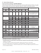
Top Vent - Horizontal Termination - (continued) Three Elbows V1 Minimum H1 Maximum V2 Minimum H2 Maximum V1 + V2 Minimum H1 + H2 Maximum 6 in. 152 mm 3 ft 914 mm 1 ft 305 mm 3 ft 914 mm 1-1/2 ft 457 mm 6 ft 1.8 m 1 ft 305 mm 3 ft 914 mm 1 ft 305 mm 3 ft 914 mm 2 ft 607 mm 6 ft 1.8 m 2 ft 610 mm 6 ft 1.8 m 2 ft 610 mm 6 ft 1.8 m 4 ft 1.4 m 12 ft 3.7 m 3 ft 914 mm 9 ft 2.7 m 3 ft 914 mm 9 ft 2.7 m 6 ft 1.8 m 18 ft 5.5 m H1 + H2 = 20 ft (6.1 m) Max.
Top Vent - Vertical Termination No Elbow V1 = 50 ft. Max. (15.2 m) V1 = 3 ft. Min. (914 mm) BREAK HERE Note: If installing a vertical vent/termination off the top of the appliance, the flue restrictor should be used. Figure 7.8 flue restrictor 2. Match the amount of vertical in the system with the chart to find the appropriate position to set the flue restrictor (see Figure 7.9).
Top Vent - Vertical Termination - (continued) V1 Two Elbows H1 Maximum V2 V1 + V2 Minimum 6 in. 152 mm 3 ft 914 mm * * * 1 ft 305 mm 3 ft 914 mm * * * 2 ft 607 mm 6 ft 1.8 m * * * 4 ft 1.2 m 12 ft 3.7 m * * * V1 + V2 + H1 = 50 ft (15.2 m) Max. *No specific restrictions on this value EXCEPT V1 + V2 + H1 cannot exceed 50 ft (15.2 m) V1 = 6 inches (152 mm) Min. V2 V1 H1 Figure 7.11 V1 Three Elbows H 1 + H2 V2 V1+ V2 Minimum H1+ H2 Maximum 6 in.
8 Vent Clearances and Framing A. Pipe Clearances to Combustibles COMBUSTIBLE SURFACE WARNING! Risk of Fire! Maintain air space clearance to vent. DO NOT pack insulation or other combustibles: • Between ceiling firestops • Between wall shield firestops • Around vent system 3 IN. MIN. (76 mm) HEAT SHIELD Failure to keep insulation or other material away from vent pipe may cause over heating and fire. 3 in. TOP CLEARANCE Note: Slope not required. 1 in. CLEARANCE AROUND VERTICAL SECTIONS 1 in.
B. Wall Penetration Framing Note: Heat shields MUST overlap by a minimum of 1-1/2 in. (38 mm). The heat shield is designed to be used on a wall 4 in. to 7-1/4 in. (102 mm to 184 mm) thick. If wall thickness is less than 4 in. (102 mm) the existing heat shields must be field trimmed. If wall thickness is greater than 7-1/4 in. (184 mm) a DVP-HSM-B will be required. 12 in. 10 in. 3 IN. TOP CLEARANCE HEAT SHIELD B HEAT SHIELD A WALL SHIELD FIRESTOP WALL 1 IN.
C. Install the Ceiling Firestop A ceiling firestop MUST be used between floors and attics. • DVP pipe only - Frame an opening 10 in. by 10 in. (254 mm by 254 mm) whenever the vent penetrates a ceiling/fl oor (see Figure 8.7). ATTIC ABOVE • Frame the area with the same sized lumber as used in ceiling/floor joist. • The ceiling firestop may be installed above or below the ceiling joists when installed with a attic insulation shield. It must be under joists between floors that are not insulated.
D. Install Attic Insulation Shield WARNING! Fire Risk. DO NOT allow loose materials or insulation to touch vent. Hearth & Home Technologies Inc. requires the use of an attic shield. BEND ALL TABS INWARD 90° TO MAINTAIN CLEARANCE AND PREVENT INSULATION FROM FALLING INSIDE The National Fuel Gas Code ANSI Z223.1 and NFPA 54 requires an attic shield constructed of 26 gauge minimum metal that extends at least 2 in. (51 mm) above insulation. Attic shields must meet specified clearance and be secured in place.
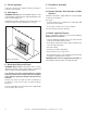
9 Appliance Preparation A. Attaching Sheetrock Ledges Attach sheetrock ledges together using the attachment holes (see Figure 9.1). DETAIL A Attach previous assembly to the top of the unit using the provided slots. The face of the sheetrock ledge assembly and the unit surround should be flush to each other. B. Temporary Access Panel Remove the lower access panel to run the electrical and gas lines to the unit (see Figure 9.3).
C. Securing and Leveling the Appliance D. Installing the Fiberglass Gasket WARNING! Risk of Fire! Prevent contact with: The fiberglass gasket supplied in the manual bag seals between the first 6 inch (203 mm) vent component and the outer fireplace wrap. Using 2 self-tapping screws from the manual bag secure the gasket to the outer wrap (see Figure 9.5).
10 Installing Vent Pipe A. Assemble Vent Sections Attach Vent to the Firebox Assembly Note: The end of the pipe sections with the lanced tabs will face toward the appliance. Attach the first pipe section to the starting collar: • Lanced pipe end to the starting collar • Inner pipe over inner collar • Push the pipe section until all lanced tabs snap in place • Lightly tug on pipe to confirm it has locked.
B. Assemble Slip Sections C. Secure the Vent Sections • Slide the inner flue of the slip section into the inner flue of the pipe section and the outer flue of the slip section over the outer flue of the pipe section. See Figure 10.6. • Vertical runs must be supported every 8 ft. (2.44 m) after the 25 ft. (7.62 m) maximum unsupported rise. • Slide together to the desired length. • Horizontal sections must be supported every 5 feet (1.52 m).
D. Disassemble Vent Sections • Rotate either section (see Figure 10.10) so the seams on both pipe sections are aligned as shown in Figure 10.11. • Pull carefully to separate the pieces of pipe. Figure 10.10 Rotate Seams for Disassembly Figure 10.11 Align and Disassemble Vent Sections 36 Heat & Glo • 6000GCF-IPI, 6000GCF-IPILP • 2110-900 Rev.
E. Install Metal Roof Flashing Note: Skip this section if using the RF4-8. • See minimum vent heights for various pitched roofs (Figure 10.14) to determine the length of pipe to extend through the roof. CAULK • Slide the roof flashing over the pipe sections extending through the roof as shown in Figure 10.15. HORIZONTAL OVERHANG 2 FT. MIN. 20 INCHES MIN. VERTICAL WALL LOWEST DISCHARGE OPENING Figure 10.15 F.
G. Install RF4-8 The RF4-8 may be used in place of the roof flashing and storm collar (Sections 10.G. and 10.H.) Pipe must be supported within 12 inches of the roofline using plumbers strapping or an SLP-FS when using the RF4-8 Flashing. Refer to Section 10.D. Secure Vent Sections. SECURE WITH 4 SCREWS NO LONGER THAN 1 IN. (25 MM) Figure 10.20 Apply Sealant SLP-FS Figure 10.18 Secure Pipe with SLP-FS • Trim the rubber boot (using scissors or a utility knife), cutting along the marked measurement lines.
H. Install Vertical Termination Cap • Attach the vertical termination cap by sliding the inner collar of the cap into the inner flue of the pipe section while placing the outer collar of the cap over the outer flue of the pipe section. • Secure the cap by driving three self-tapping screws (supplied) through the pilot holes in the outer collar of the cap into the outer flue of the pipe (see Figure 10.23). TERMINATION CAP I.
J. Install Horizontal Termination Cap WARNING! Risk of Fire! The telescoping flue section of the termination cap MUST be used when connecting vent. • 1-1/2 (38 mm) minimum overlap of flue telescoping section is required. Failure to maintain overlap may cause overheating and fire. Note: When using termination caps with factory-supplied heat shield attached, no additional wall shield firestop is required on the exterior side of a combustible wall. HEAT SHIELD OR EXTENDED HEAT SHIELD HEAT SHIELD 1-1/2 IN.
11 Gas Information A. Fuel Conversion C. Gas Connection • Make sure the appliance is compatible with available gas types. • Refer to Reference Section 16 for location of gas line access in appliance. • Conversions must be made by a qualified service technician using Hearth & Home Technologies specified and approved parts. • Gas line may be run through knockout(s) provided. B. Gas Pressure • Optimum appliance performance requires proper input pressures.
12 Electrical Information A. Wiring Requirements B. Intellifire Ignition System Wiring NOTICE: This appliance must be electrically wired and grounded in accordance with local codes or, in the absence of local codes, with National Electric Code ANSI/NFPA 70-latest edition or the Canadian Electric Code CSA C22.1. • Wire the appliance junction box to 110-120 VAC. This is required for proper operation of the appliance (Intellifire ignition).
WARNING! Risk of Shock! Replace damaged wire with type 105º C rated wire. Wire must have high temperature insulation. D. Electrical Service and Repair WARNING! Risk of Shock! Label all wires prior to disconnection when servicing controls. Wiring errors can cause improper and dangerous operation. Verify proper operation after servicing.
E. Junction Box Installation If the box is being wired from the INSIDE of the appliance: Romex Connector • Remove the screw attaching the junction box/receptacle to the outer shell, rotate the junction box inward to disengage it from the outer shell (see Figure 12.4). 14/2WG • Pull the electrical wires from outside the appliance through the opening into the valve compartment and secure wires with a Romex connector. See Figure 12.4.
13 Finishing A. Mantel and Wall Projections B. Facing Material WARNING! Risk of Fire! Comply with all minimum clearances as specified. Framing closer than the minimums listed must be constructed entirely of noncombustible materials (i.e., steel studs, concrete board, etc.) Failure to comply could cause fire. • Metal front faces may be covered with non-combustible materials only. • Facing and/or finishing materials must never overhang into the glass opening.
14 Appliance Setup A. Remove Fixed Glass Assembly See Section 14.I. B. Remove the Shipping Materials Remove shipping materials from inside or underneath the firebox. C. Clean the Appliance Clean/vacuum any sawdust that may have accumulated inside the firebox or underneath in the control cavity. D. Accessories Install approved accessories per instructions included with accessories. Contact your dealer for a list of approved accessories.
F. Install the Refractory STEP 3. Note: The red refractory will naturally darken when the firebox heats up. The red color will return when the firebox cools. Repeat step 2 for the right side. STEP 1. Place the back piece of refractory in back of the firebox. The small indentation on one side goes down. Lean the refractory slightly so it doesn’t tip over. Figure 14.6 G. Ember Placement Figure 14.4 WARNING! Risk of Explosion! Follow ember placement instructions in manual.
H. Install the Log Assembly Log Assembly: LOGS-6000G If the gas logs have been factory installed they should not need to be positioned. If the logs have been packaged separately, refer to the following instructions. 1 STEP 1. CAUTION: Logs are fragile! Carefully remove the logs, grate and supporting cardboard from the inside of the fireplace See Figure 14.8. 3 4 2 5 STEP 2. Place the metal grate on top of the burner.
2 2 Figure 14.12 Front View Figure 14.13 Top View STEP 4. Log #2 (SRV2103-108): Place log #2 on top of the left side of log #1. The bottom of this log has a slot in it that goes over the tab molded into the top of log #1. The left end sits behind the simulated ember cluster on the burner top. 3 3 Figure 14.14 Front View Figure 14.15 Top View STEP 5. Log #3 (SRV2103-110): Place log #3 on top of the burner surface in front of the hump. The bottom of the log has a square groove cut through it.
I. Fixed Glass Assembly M. Air Shutter Setting WARNING! Risk of Asphyxiation! Handle fixed glass assembly with care. Inspect the gasket to ensure it is undamaged and inspect the glass for cracks, chips or scratches. Air shutter settings should be adjusted by a qualified service technician at the time of installation. The air shutter is set at the factory for minimum vertical vent run. Adjust air shutter for longer vertical runs. See Figure 14.21. • DO NOT strike, slam or scratch glass.
15 Troubleshooting With proper installation, operation, and maintenance your gas appliance will provide years of trouble-free service. If you do experience a problem, this troubleshooting guide will assist a qualified service technician in the diagnosis of a problem and the corrective action to be taken. This troubleshooting guide can only be used by a qualified service technician. Contact your dealer to arrange a service call by a qualified service technician. A.
Intellifire Ignition System - (continued) Symptom 4. Pilot lights but continues to spark, and main burner will not ignite. (If the pilot continues to spark after the pilot flame has been lit, flame rectification has not occurred.) 52 Possible Cause A. A shorted or loose connection in flame sensing rod. Corrective Action Verify all connections to wiring diagram in manual. Verify connections underneath pilot assembly are tight.
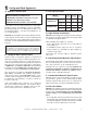
16 Reference Materials A. Appliance Dimension Diagram Dimensions are actual appliance dimensions. Use for reference only. For framing dimensions and clearances refer to Section 5.
B. Vent Components Diagrams Pipe DVP4 Effective Height/Length DVP Pipe (see chart) Effective Length Inches Millimeters 4 102 10-1/2 in. (267 mm) 45 ° DVP6 6 152 DVP12 12 305 DVP24 24 610 DVP36 36 914 DVP48 48 1219 10-7/8 in. (276 mm) DVP45 (45º Elbow) 4-7/8 in. ( 276 mm) DVP6A 3 to 6 76 to 152 DVP12A 3 to 12 76 to 305 DVP12MI 3 to 12 76 to 305 DVP24MI 3 to 24 76 to 610 11-3/8 in. (289 mm) 10 in. (254 mm) 10 in. (254 mm) 1 in. (25 mm) 7-3/8 in. (187 mm) 24 in.
B. Vent Components Diagrams (continued) Note: Heat shields MUST overlap by a minimum of 1-1/2 in. (38 mm). The heat shield is designed to be used on a wall 4 in. to 7-1/4 in. (102 mm to 184 mm) thick. If wall thickness is less than 4 in. (102 mm) the existing heat shields must be field trimmed. If wall thickness is greater than 7-1/4 in. (184 mm) a DVP-HSM-B will be required. 8 in. (203 mm) Heat Shield 15-1/8 in. (384 mm) Term Cap 12 in.
B. Vent Components Diagrams (continued) 7-3/8 in. 1-1/2 in. 3-7/8 in. 17-3/4 in. 14 in. 10-1/2 in. DVP-TV Vertical Termination Cap Not for use on these models. 12 in. DVP-TB1 Basement Vent Cap 31 in. 13-1/4 in. 24-5/8 in. 27-1/2 in. 24-5/8 in. 13-1/4 in. RF12M Roof Flashing Multi-pak RF6M Roof Flashing Multi-pak 13-3/4 in. DVP-TRAPFL Flashing 5 in. 7-1/4 in. 12-1/2 in. 13-3/4 in. 5-1/4 in. DVP-TVHW Vertical Termination Cap (High wind) BEK Trap Cap Brick Extension 9-1/2 in. 13-7/8 in.
B. Vent Components Diagrams (continued) 8-1/8 in. (206 mm) 13 in. (330 mm) Effective Length 5-3/4 to 8-3/8 in. 146 to 213 mm 5-1/2 in. 140 mm 87° 8-3/8 in. 213 mm 3° 15 in. (381 mm) 10-1/2 in. 267 mm 10-7/8 in. 276 mm WARNING Fire Risk. • When using SL-HRC-SS and SL-HRC-ZC-SS termination caps on top vented fireplaces, a six inch minimum vertical vent section is required before installing first elbow. DVP-HRC-SS DVP-HRC-ZC-SS HORIZONTAL TERMINATION CAP Figure 16.
6000GCF-IPI C. Service Parts Beginning Manufacturing Date: May 2006 Ending Manufacturing Date: ______ Service Parts Diagram 8 6 7 9 10 12 11 Log Set Assembly 1 2 3 5 Part number list on following page. 58 Heat & Glo • 6000GCF-IPI, 6000GCF-IPILP • 2110-900 Rev.
C. Service Parts List 6000GCF-IPI IMPORTANT: THIS IS DATED INFORMATION. When requesting service or replacement parts for your appliance please provide model number and serial number. All parts listed in this manual may be ordered from an authorized dealer.
00GCF-IPI Service Parts Beginning Manufacturing Date: May 2006 Ending Manufacturing Date: ______ Valve Assembly Diagram/ Parts List 1 Intermittent Pilot Ignition Valve Assembly 12 11 2 3 5 10 4 8 9 6 7 IMPORTANT: THIS IS DATED INFORMATION. When requesting service or replacement parts for your appliance please provide model number and serial number. All parts listed in this manual may be ordered from an authorized dealer.
D. Contact Information Heat & Glo, a brand of Hearth & Home Technologies Inc. 7571 215th St, Lakeville, MN 55044 www.heatnglo.com Please contact your Heat & Glo dealer with any questions or concerns. For the location of your nearest Heat & Glo dealer, please visit www.heatnglo.com.