R CB1200-I PELLET INSERT Owner’s Manual Installation and Operation O-T L Tested and Listed by C Portland Oregon USA US OMNI-Test Laboratories, Inc. Model: CB1200I-B NOTICE • Important operating and • Read, understand and • Leave this manual with follow these instrucparty responsible for use maintenance instructions for safe installaand operation. tions included. tion and operation.
R CB1200-I Pellet Insert and Welcome to the Quadra-Fire Family! Hearth & Home Technologies welcomes you to our tradition of excellence! In choosing a Quadra-Fire appliance, you have our assurance of commitment to quality, durability, and performance. This commitment begins with our research of the market, including ‘Voice of the Customer’ contacts, ensuring we make products that will satisfy your needs.
R CB1200-I Pellet Insert TABLE OF CONTENTS Section 1: Listing and Code Approvals A. B. C. D. E. Section 8: Operating Instructions Appliance Certifications ......................4 Mobile Home Approved ......................4 Glass Specifications ............................4 Electrical Rating ..................................4 BTU & Efficiency Specifications ..........4 A. B. C. D. E. F. G. H. Section 2: Getting Started A. Design, Installation & Location Considerations ....................................
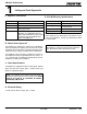
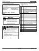
R CB1200-I Pellet Insert 1 Listing and Code Approvals A. Appliance Certification E. BTU & Efficiency Specifications MODEL: 1200-I Pellet Insert Emissions Rating: .9 grams/hr LABORATORY: OMNI Test Laboratories, Inc *BTU Output: 14,000 - 40,000 / hr REPORT NO. 061-S-13-2 Heating Capacity: TYPE: Solid Fuel Room Heater/Pellet Fuel Burning Type Insert up to 2,500 sq. ft.
R 2 CB1200-I Pellet Insert Getting Started A. Design, Installation & Location Considerations B. Fire Safety 1. Appliance Location Consideration must be given to safety, convenience, traffic flow, and the fact that the appliance will need a chimney and chimney connector. It is a good idea to plan your installation on paper, using exact measurements for clearances and floor protection, before actually beginning the installation.
R CB1200-I Pellet Insert D. Inspect Appliance & Components and Pre-Use Check List C. Tools And Supplies Needed Tools and building supplies normally required for installation, unless installing into an existing masonry fireplace: 1. Place the appliance in a location near the final installation area and follow the procedures below: 2. Open the appliance and remove all the parts and articles packed inside the Component Pack. Inspect all the parts and glass for shipping damage.
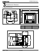
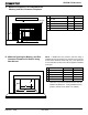
R 3 CB1200-I Pellet Insert Dimensions and Clearances A. Appliance Dimensions B 40" (1016mm) 29-1/4" (743mm) 22" (559mm) 8-3/4" (222mm) 13" (330mm) 10-3/4" (273mm) A 12" (305mm) 28-1/2" (724mm) Figure 7.1 - Top View Figure 7.
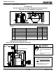
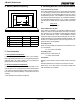
R CB1200-I Pellet Insert B. Clearance To Combustibles, UL and ULC AS A BUILT-IN Rear Shroud Kit, Part 811-0680 is Required for Built-In Installation (see pages 17-18 for installation instructions) D A B C B C E 0 INCH (0mm) CLEARANCE TO EXPOSED SECTION AND FACE TRIM Figure 8.1 A Top of Shroud Inches Millime- Top Vent 3.0 76 Rear Vent 0 0 0 0 B Sides of Inside Shroud Top or Rear Vent C Back of Inside Shroud Top Vent 2.5 64 Rear Vent 0 0 3.
R CB1200-I Pellet Insert C. Minimum Clearances To Combustibles for Masonry and Zero Clearance Fireplaces MANTEL Face Trim SIDE WALL B C Inches Millimeters A Louvers to combustible side wall 6 153 B Insert top to mantel 12 305 C Top to Face Trim 3 76 D Hearth Extension - Front 6 153 E Hearth Extension - Sides 8 203 A D E Figure 9.1 D.
R CB1200-I Pellet Insert E. Masonry Minimum Opening G. Calculating Alternate Floor Protection Material Thermal Conductivity: k value The k value indicates the amount of heat (in BTU’s) that will flow in 1 hour through 1 square foot of a uniform material 1 inch thick for each degree (F) of temperature difference from one side of the material to the other. The LOWER the k factor means less heat is being conducted through the non-combustible material to the combustible material beneath it.
R CB1200-I Pellet Insert H. Removing Metal Floor of Factory-Built Firebox • The firebrick (refractory), glass doors, screen rails, screen mesh and log grates can be removed from a factory-built firebox in order to gain minimum insert opening requirements. • Any smoke shelves, shields and baffles may be removed from a factory-built firebox if attached with mechanical fasteners.
R CB1200-I Pellet Insert 4 Vent Information B. Venting Termination Requirements A. Chimney and Exhaust Connection 1. Chimney & Connector: Use 3 or 4 inch (76-102mm) diameter type "L" or "PL" venting system. It can be vented vertically or horizontally. 2. Mobile Home: Approved for all Listed pellet vent. Use Listed double wall flue connector. A Quadra-Fire Outside Air Kit must be used with manufactured home installations. 3.
R CB1200-I Pellet Insert WARNING C. Equivalent Feet of Pipe Improper installation, adjustment, alteration, service or maintenance can cause injury or property damage. Refer to the owner’s information manual provided with this appliance. For assistance or additional information consult a qualified installer, service agency or your dealer. The table below can help you calculate the equivalent feet of pipe which is a method used to determine pellet vent size. See Figure 13.1.
R CB1200-I Pellet Insert 5 Venting Systems B. Direct Connect Without Outside Air A. Direct Connect With Outside Air NOTE: In Canada, only a full reline is allowed per ULC S-628, ORD ULC C1482. NOTE; Use metal plate around exhaust vent pipe and seal all edges with non-flammable insulation such as fiberglass, mineral wool or ceramic material. Do not use high temperature caulking materials to seal any edge to prevent future serviceability. Outside Air through Rear Wall Figure 14.1 Figure 14.
R CB1200-I Pellet Insert C. Full Reline With Outside Air NOTE: Check clearances carefully for this type of installation to ensure adequate room for outside air venting. 12” (305mm) min. above 12” (305mm) min. below NOTE: In Canada, only a full reline is allowed per ULC S-628, ORD ULC C1482. CAUTION Check building codes prior to installation. • Installation MUST comply with local, regional, state and national codes and regulations.
R CB1200-I Pellet Insert 6 Mobile Home A. Mobile Home Installation You must use a Quadra-Fire Outside Air Kit for installation in a mobile home. 1. An outside air inlet must be provided for the combustion air and must remain clear of leaves, debris, ice and/or snow. It must be unrestricted while the appliance is in use to prevent room air starvation which causes smoke spillage. Smoke spillage can also set off smoke alarms. 2. The combustion air duct system must be made of metal.
R 7 CB1200-I Pellet Insert Appliance Set-Up A. Rear Shroud Installation 1. Top Vent Installations Parts Required: REAR SHROUD TOP VENT PART 811-0 0 Part 811-0680, Rear Shroud Kit. Includes: Six galvanized steel shroud pieces, two cover plates and fastener package. Part 811-0650, Rear Shroud Top Vent Includes: Vent pipe and two 1/4 - 20 x 3/4 inch bolts with nuts.
R CB1200-I Pellet Insert Rear Vent Installation Preparation: 1. Remove the ENTIRE exhaust blower housing by removing the 4 nuts using a 7/16 inch socket wrench. Set the nuts aside for later use. 2. Remove the 4 screws and remove the vertical exhaust transition pipe exhaust blower housing. 3. Remove any silicone sealant remaining on the blower housing. 4. Attach the rear vent adapter to the exhaust blower housing with 4 screws. Figure 18.2. 5. 6. 7. 8. 9. 4.
R CB1200-I Pellet Insert C. Adjustable Hopper Options B. Outside Air Kit Instructions Depending on your installation, the hopper can be vertically adjusted up to a maximum of 3-1/2 inches (89mm) and will hold an additional 15 lbs of fuel. Parts Included in Kit: 1 piece of 2 inch x 3 ft. flex hose, 1 hose clamp and 1 rodent screen. Tools Needed: Phillips head screw driver; wire cutters; hole saw or jig saw. 1. Measure distance from floor to air vent opening in appliance and mark location on wall.
R CB1200-I Pellet Insert E. Adjustable Hearth Support EXPLODED VIEW OF SCISSORS Size: 9”d x 45”w, 2” to 10” Height Adjustment Included in Kit: (1) trim top, (1) trim front, (2) trim sides, double-sided tape (already installed) SCREWS ARE CIRCLED Tools Needed: Phillips head screw driver, sheet metal shears, measuring tape, gloves 1. The 10 screws on each set of scissors will already be loose when shipped. Figure 20.1. DOUBLE-SIDED TAPE DOUBLE-SIDED TAPE Figure 20.1 2.
R CB1200-I Pellet Insert F. Panel and Trim Set Standard Size: 30 inches H x 40 inches W (762mm x 1016mm) Large Size: 33 inches H x 50 inches W (838mm x 1270mm) Included in Kit: 2 side panels, 1 top panel, 2 side trim, 1 top trim, 2 corner brackets and fastener package. Tools Needed Phillips and flat head screw drivers. 1. Unpack and lay out parts face down (flanges up) on a nonabrasive surface as shown in Figure 21.1. Install (1) 8-32 x 3/8 inch screw into bottom tab of side panel. Figure 21.3 2.
R CB1200-I Pellet Insert F. Panel and Trim Set (Cont’d) 5. Hold side curtains in open position and lower panel set over insert setting lower edge of top panel in slot between hopper lid and panel support as shown in Figure 22.1. Place existing screw head (installed in Figure 21.2) into locator hole in floor of insert. Figure 22.2. 6. Lift hopper lid and press down on panel top while installing (4) 8-32 x 3/8 inch screws into holes in panel support.
R CB1200-I Pellet Insert G. Optional Brick Set Installation WARNING 1. Slide bottom of left rear brick in first; rotate top edge toward rear of appliance and then rotate outer edge toward rear of appliance, until brick slides into place. Figure 23.1. Repeat for right rear brick. 2. Place left side brick along left side of firebox, making sure chamfered (beveled) back edge fits snugly next to left rear brick. Figure 23.2. Repeat with right side brick. 3. Complete brick set, correctly installed.
R CB1200-I Pellet Insert I. Optional Log Set Placement Instructions J. Thermostat Installation CAUTION 1. A 12 volt AC thermostat is required to operate this pellet appliance. You may use the included wall mount thermostat or purchase an optional programmable thermostat or remote control. The included thermostat is equipped with an adjustable heat anticipator. The current rating is .05 amps. The anticipator needs to be adjusted to the lowest setting available. 2.
R 8 CB1200-I Pellet Insert Operating Instructions A. Fuel Size And Material B. General Operating Information 1. Wood Pellets 1. Thermostat Calls For Heat Fuel pellets are made from sawdust or wood by-products. If the source material is hardwood, they can have a higher mineral content, creating more ash. Fuels containing bark will also have higher ash content.
R CB1200-I Pellet Insert C. Before Your First Fire E. Fire Characteristics 1. First, make sure your appliance has been properly installed and that all safety requirements have been met. Pay particular attention to the fire protection, venting and thermostat installation instructions. 3. Check the position of the thermocouple, located above the firepot, and make sure that it protrudes approximately 3/4 inch (19mm) into the firepot.
R CB1200-I Pellet Insert WARNING Fire Risk Do NOT operate appliance: • With appliance door open. • Firepot floor open. • Cleaning slide plates open. Do NOT store fuel: • Closer than required clearances to combustibles to appliance • Within space required for loading or ash removal. Back side of Firepot Firepot floor left open Figure 27.1 - DO NOT LEAVE FIREPOT FLOOR OPEN H. Frequently Asked Questions ISSUES SOLUTIONS 1. Metallic noise. 1.
R CB1200-I Pellet Insert 9 With proper installation, operation, and maintenance your appliance will provide years of trouble-free service. If you do experience a problem, this troubleshooting guide will assist a qualified service person in the diagnosis of a problem and the corrective action to be taken. This troubleshooting guide can only be used by a qualified service technician. Troubleshooting Possible Cause Symptom Plug in appliance - No response. Call light on. No fire. No fuel in firepot.
R CB1200-I Pellet Insert Troubleshooting (Cont’d) Symptom Possible Cause Corrective Action Slow or smoky start-up (Cont’d) Dirty exhaust and/or venting system. Check for ash build up in appliance, including behind rear panels, firebox, heat exchanger, exhaust blower and venting. Feed system fails to start. Out of fuel. Check hopper, fill with fuel. #2 snap disc may be defective. Replace snap disc. Firebox door must be closed securely. Vacuum switch not closing. No vacuum.
R CB1200-I Pellet Insert Troubleshooting (Cont’d) Symptom Convection blower fails to start. Exhaust blower fails to start or does not shut off. Large, lazy flame, orange color. Black ash on glass. Possible Cause No call light. Defective control box. #1 snap disc defective. Replace snap disc. Blower not plugged in. Check that blower is plugged into wire harness. Blower is defective. Replace blower. Control box is defective. Replace control box. Blower not plugged in.
R 10 CB1200-I Pellet Insert Maintaining & Servicing Your Appliance C. General Maintenance A. Proper Shutdown Procedure 1. Types of Fuel CAUTION Depending on the type of fuel you are burning will dictate how often you have to clean your firepot. Shock and Smoke Hazard If the fuel you are burning has a high dirt or ash content or you are burning shelled field corn, it may be necessary to clean the firepot more than once a day.
R CB1200-I Pellet Insert 2. Cleaning Firepot with Cleaning Rod & Firepot Clean-Out Tool • • 4. Cleaning Ash Pan • • Frequency: Daily or more often as needed By: Homeowner Frequency: Weekly or every 5 bags of fuel By: Homeowner Locate the ash pan underneath the firepot and using a slight pull up and out remove the ash pan. Empty into a non-combustible container and re-install ash pan. See Disposal of Ashes. a. Be sure the appliance is allowed to cool, has been unplugged and the exhaust blower is off.
R CB1200-I Pellet Insert 7. Cleaning Beneath Heat Exchanger • • 10. Door Latch Inspection Frequency: Monthly or after burning 1 ton of fuel By: Homeowner • • a. Be sure the appliance is allowed to cool, has been unplugged and the exhaust blower is off . a. Be sure the appliance is allowed to cool, has been unplugged and the exhaust blower is off b. A more thorough cleaning is needed to remove the excess ash that is left behind from the use of the cleaning rods for the heat exchanger tubes. b.
R CB1200-I Pellet Insert 15. Soot and Fly Ash: Formation & Need for Removal in Exhaust Venting System. • • Frequency: Yearly or more frequently depending on ash build-up. By: Qualified Service Technician/Homeowner Be sure the appliance is allowed to cool, has been unplugged and the exhaust blower is off. The products of combustion will contain small particles of fly ash. The fly ash will collect in the exhaust venting system and restrict the flow of the flue gases.
R CB1200-I Pellet Insert D. High Ash Fuel Content Maintenance • • Frequency: When the ash build-up exceeds more than half way up the firepot. By: Homeowner Pellets Back Up In Feed Tube Firepot Overfills Poor quality pellet fuel, or lack of maintenance, can create conditions that make the firepot fill quickly with ashes and clinkers. This condition makes the appliance susceptible to overfilling the firepot with pellets which may result in smoking, sooting and possible hopper fires. Figure 35.
R CB1200-I Pellet Insert E. Glass Replacement oor Latc WARNING o otto ra e • Glass is 5mm thick high temperature heatresistant ceramic glass. • DO NOT REPLACE with any other material. Center Posts • Alternate material may shatter and cause injury • Remove door from appliance and place face down on a protected surface to avoid scratching the door. Side ra e lass • Remove all door rope. 1.
R CB1200-I Pellet Insert F. Igniter Replacement G. Baffle Removal a. Be sure the appliance is allowed to cool, has been unplugged and the exhaust blower is off. b. Open glass door. c. Grasp the bottom of the baffles and pull up to dislodge from hook attachment. d. Use a standard screw driver to unlatch the covers beneath the baffles of each side. e. Re-install in reverse order. niter racket u Scre niter Figure 37.1 a.
R CB1200-I Pellet Insert 11 Reference Materials A. Component Function 1. Control Box a. The control box is located on right side of appliance, behind the right side panel. b. There is a light located inside of the control box. The internal light will turn green when the appliance has reached a temperature of 200οF (93°C) in the firepot. and will turn red when it reaches 600oF (315°C). When describing the location of a component part it is always AS YOU FACE THE FRONT OF THE APPLIANCE. 7.
R CB1200-I Pellet Insert 16. Snap Disc #1 (Convection Blower) 125°F 19. Vacuum Switch Snap disc #1 is located on the right side of the firebox. There are 2 purple wires connected to it. This snap disc turns the convection blower on and off as needed. Power is always present at snap disc #1. The vacuum switch is located at the rear of the appliance. This switch turns the feed system on when vacuum is present in the firebox.
R CB1200-I Pellet Insert B. Component Locations Terminal Block Center 2 Screws for Thermostat Wires Control Box Heat Output Switch Reset Button Red Call Light Fuse Blue Blinking Light Red/ Green Light Power Outlet Figure 40.1 Exhaust Transition Assembly Convection Blower Exhaust Blower Figure 40.
R CB1200-I Pellet Insert C.
R CB1200-I Pellet Insert 27 26 28 25 29 32 33 30 31 23 24 22 34 38 36 35 37 19 39 20 21 18 17 40 16 41 42 15 43 14 13 11 12 Figure 42.
R CB1200-I Pellet Insert D. Service Parts and Accessories IMPORTANT: This is dated information. The most current information is located on the quadra-fire web site at www.Quadrafire.Com. When ordering, supply serial and model numbers to ensure correct part.
R CB1200-I Pellet Insert Item # Part Descsription, Alphabetical Order SKU Feed Spring Only SRV7027-024 Firepot Bolt, 1-1/4” long 225-0120 Firepot Floor (Slide Plate) 414-0290 Firepot Nut, 1/4-20 226-0090 40 Firepot Pull Rod Assembly (Linkage) 812-4140 41 Firepot, EZ Clean 812-3351 Fuse .
R Item No. CB1200-I Pellet Insert Accessories Part No.
R CB1200-I Pellet Insert E. Warranty Policy Hearth & Home Technologies LIMITED WARRANTY Hearth & Home Technologies (“HHT”) and its respective brands extends the following warranty for HHT gas, wood, pellet and electric appliances purchased from an authorized HHT dealer and installed in the United States of America or Canada. Warranty starts with date of purchase by the original owner (End User) except as noted for replacement parts.
R CB1200-I Pellet Insert Hearth & Home Technologies LIMITED WARRANTY (Cont’d) HHT’s obligation under this warranty does not extend to damages resulting from: (1) installation, operation or maintenance of the appliance not in accordance with the installation instructions; operating instructions and the listing agent identification label furnished with the appliance; (2) installation which does not comply with local building codes; (3) shipping, improper handling, improper operation, abuse, misuse, accid
R O T T O TO : Hearth & Home Technologies 1445 North Highway Colville, WA 99114 Division of HNI INDUSTRIES www.quadrafire.com Please contact your Quadra-Fire dealer with any questions or concerns. For the number of your nearest Quadra-Fire dealer visit our website at www.quadrafire.com NOTICE • Important operating and • Read, understand and follow these instrucmaintenance instructions for safe installations included. tion and operation.