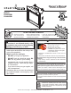
Owner’s Manual Installation and Operation Models: BV4236DBI BV4842DBI NOTICE DO NOT DISCARD THIS MANUAL • Important operating and maintenance instructions included. • Read, understand and follow these instructions for safe installation and operation. WARNING: If the information in these instructions is not followed exactly, a fire or explosion may result causing property damage, personal injury, or death.
Read this manual before installing or operating this appliance. Please retain this owner’s manual for future reference. A. Congratulations This owner’s manual should be retained for future reference. We suggest that you keep it with your other important documents and product manuals. Congratulations on selecting a Hearth & Home Technologies gas fireplace, an elegant and clean alternative to wood burning fireplaces.
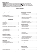
Safety Alert Key: • • • • DANGER! Indicates a hazardous situation which, if not avoided will result in death or serious injury. WARNING! Indicates a hazardous situation which, if not avoided could result in death or serious injury. CAUTION! Indicates a hazardous situation which, if not avoided, could result in minor or moderate injury. NOTICE: Used to address practices not related to personal injury. Table of Contents A. Congratulations . . . . . . . . . . . . . . . . . . . . . . . . . . . . . . . . .
E. Burner Top Installation. . . . . . . . . . . . . . . . . . . . . . . . . . . . 37 F. G. H. I. J. K. Lava Rock Placement . . . . . . . . . . . . . . . . . . . . . . . . . . . . Ember Placement. . . . . . . . . . . . . . . . . . . . . . . . . . . . . . . . Install the Log Assembly. . . . . . . . . . . . . . . . . . . . . . . . . . Fixed Glass Assembly . . . . . . . . . . . . . . . . . . . . . . . . . . . . Install Trim and/or Surround. . . . . . . . . . . . . . . . . . . . . . . . Air Shutter Setting .
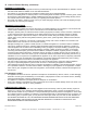
B. Limited Lifetime Warranty Hearth & Home Technologies Inc. LIMITED LIFETIME WARRANTY Hearth & Home Technologies Inc., on behalf of its hearth brands (”HHT”), extends the following warranty for HHT gas, wood, pellet, coal and electric hearth appliances that are purchased from an HHT authorized dealer.
B. Limited Lifetime Warranty (continued) WARRANTY CONDITIONS: • • • • This warranty only covers HHT appliances that are purchased through an HHT authorized dealer or distributor. A list of HHT authorized dealers is available on the HHT branded websites. This warranty is only valid while the HHT appliance remains at the site of original installation. Contact your installing dealer for warranty service.
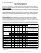
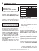
1 Listing and Code Approvals A. Appliance Certification MODELS: BV4236DBI, BV4842DBI LABORATORY: Underwriters Laboratories, Inc. (UL) TYPE: B-Vent Gas Appliance STANDARD: ANSI Z21.50b-2009 • CSA 2.22b-2009 This product is listed to ANSI standards for “Vented Gas Fireplaces” and “Gas Fired Appliances for Use at High Altitudes”. May be installed in a sleeping room when the provisions for combustion, ventilation and dilution air are met per the requirements of ANSI 223.1/NFPA 54 National Fuel Gas Code.
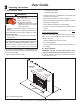
2 Operating Instructions User Guide A. Gas Fireplace Safety - A decorative firescreen. - Adjustable safety gate. WARNING HOT SURFACES! Glass and other surfaces are hot during operation AND cool down. Hot glass will cause burns. • DO NOT touch glass until it is cooled • NEVER allow children to touch glass • Keep children away • CAREFULLY SUPERVISE children in same room as fireplace. • Alert children and adults to hazards of high temperatures.
C. Fan Kit (optional) For safety: If desired, a fan kit may be added. Contact your dealer to order the correct fan kit. • Install a switch lock or a wall/remote control with child protection lockout feature. D. Clear Space • Keep remote controls out of reach of children. WARNING! DO NOT place combustible objects in front of the fireplace or block louvers. High temperatures may start a fire. See Figure 2.2. See your dealer if you have questions. H.
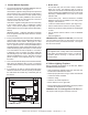
J. Control Module Operation 5. Module Reset This module may lock-out under certain conditions. When this occurs, the appliance will not ignite or respond to commands. The module will go into lock-out mode by emitting three audible beeps, then continuously displaying a RED/GREEN error code at its status indicator LED. 1. The control module has an ON/OFF/REMOTE selector switch that must be set. See Figure 2.3.
L. Lighting Instructions (IPI) FOR YOUR SAFETY READ BEFORE LIGHTING LIGHTING INSTRUCTIONS (IPI) WARNING: If you do not follow these instructions exactly, a fire or explosion may result causing property damage, personal injury or loss of life. 1. This appliance is equipped with an ignition device which automatically lights the burner. DO NOT try to light the burner by hand. A. This appliance is equipped with an intermittent pilot ignition (IPI) device which automatically lights the burner.
M. After Fireplace is Lit Initial Break-in Procedure • The fireplace should be run three to four hours continuously on high. • Turn the fireplace off and allow it to completely cool. • Remove fixed glass assembly. See Section 14.I. • Clean fixed glass assembly. See Section 3. • Replace the fixed glass assembly and run continuously on high an additional 12 hours. This cures the materials used to manufacture the fireplace. NOTICE! Open windows for air circulation during fireplace break-in.
3 Maintenance and Service Any safety screen or guard removed for servicing must be replaced prior to operating the fireplace. Doors, Surrounds, Fronts Frequency: Annually When properly maintained, your fireplace will give you many years of trouble-free service. We recommend annual service by a qualified service technician. By: Homeowner A. Maintenance Tasks-Homeowner • Inspect for scratches, dents or other damage and repair as necessary.
B. Maintenance Tasks-Qualified Service Technician Burner Ignition and Operation The following tasks must be performed by a qualified service technician. By: Qualified Service Technician Gasket Seal and Glass Assembly Inspection Frequency: Annually By: Qualified Service Technician Tools needed: Protective gloves, drop cloth and a stable work surface. • Inspect gasket seal and its condition. • Inspect fixed glass assembly for scratches and nicks that can lead to breakage when exposed to heat.
C. Lava Rock Basket, Grate and Valve Assembly Removal It may become necessary to remove the lava rock basket, grate and valve assemblies. This task should be performed by a qualified service technician. The grate and lava rock basket do not need to be removed to service the burner assembly. Figure 3.2 Grate Removal Note: The cover plates must be removed to access screws. COVER PLATES Figure 3.3 Lava Rock Basket Figure 3.
D. Burner Identification/Verification The burner may be accessed for identification and verification purposes. This task should be performed by a qualified service technician. The base refractory, valve plate, optional refractory and grate do not need to be removed to access the burner assembly. The logs and fiber burner top need to be removed to access the burner. Disconnect the pilot from the burner before removal. See Figure 3.5 for burner identification chart.
4 Getting Started Installer Guide A. Typical Appliance System NOTICE: Illustrations and photos reflect typical installations and are for design purposes only. Illustrations/diagrams are not drawn to scale. Actual product may vary from pictures in manual VERTICAL TERMINATION CAP (SECTION 6) NON-COMBUSTIBLE ROOF FLASHING MAINTAINS MINIMUM CLEARANCE AROUND PIPE (SECTION 4.D) STORM COLLAR (SECTION 4.D) VENT PIPE PENETRATES ROOF PREFERABLY WITHOUT AFFECTING ROOF RAFTERS (SECTION 8.
B. Design and Installation Considerations • Termination Cap Hearth & Home Technologies B-type vent gas appliances are designed to operate with all exhaust gases expelled to the outside of the building, and combustion air pulled from the room. • Storm Collar Installation MUST comply with local, regional, state and national codes and regulations. Consult insurance carrier, local building inspector, fire officials or authorities having jurisdiction over restrictions, installation inspection and permits.
E. Negative Pressure WARNING! Asphyxiation Risk! Negative pressure can cause spillage of combustion fumes and soot. Fireplace needs to draft properly for safety. Draft is the pressure difference needed to vent fireplaces successfully. Considerations for successful draft include: • Preventing negative pressure • Location of fireplace and chimney Negative pressure results from the imbalance of air available for the fireplace to operate properly.
5 Framing and Clearances A. Selecting Appliance Location NOTICE: Illustrations reflect typical installations and are FOR DESIGN PURPOSES ONLY. Illustrations/diagrams are not drawn to scale. Actual installation may vary due to individual design preference. When selecting a location for the appliance it is important to consider the required clearances to walls (see Figure 5.1). WARNING! Risk of Fire or Burns! Provide adequate clearance around air openings and for service access.
B. Constructing the Appliance Chase Walls, ceiling, base plate and cantilever floor of the chase should be insulated. Vapor and air infiltration barriers should be installed in the chase as per regional codes for the rest of the home. Additionally, in regions where cold air infiltration may be an issue, the inside surfaces may be sheetrocked and taped for maximum air tightness. A chase is a vertical box-like structure built to enclose the gas appliance and/or its vent system.
C. Clearances D. Mantel and Wall Projections NOTICE: Install appliance on hard metal or wood surfaces extending full width and depth. DO NOT install directly on carpeting, vinyl, tile or any combustible material other than wood. WARNING! Risk of Fire! Comply with all minimum clearances as specified. Framing or finishing material closer than the minimums listed must be constructed entirely of noncombustible materials (i.e., steel studs, concrete board, etc).
6 Termination Locations A. Vent Termination Minimum Clearances A WARNING 18 in. minimum 457 mm 20 in. and over 0 in. minimum Gas, Wood or Fuel Oil Termination Cap Fire Risk. Maintain vent clearance to combustibles as specified. • DO NOT pack air space with insulation or other materials. Failure to keep insulation or other materials away from vent pipe may cause overheating and fire. 8 FEET LISTED B-VENT TERMINATION CAP VERTICAL WALL LOWEST DISCHARGE OPENING 12 X ROOF PITCH IS X/ 12 H (MIN.
7 Vent Information and Diagrams A. Vent Guidelines WARNING! Fire Risk/Asphyxiation! This appliance requires the specified pipe for operation. Incorrect pipe may cause spillage, condensation and overheating. MINIMUM CLEARANCES ARE PER VENT MANUFACTURER’S SPECIFICATIONS These models require the following size B-vent double wall, or single wall rigid or flex vent pipe.
8 Vent Clearances and Framing A. Pipe Clearances to Combustibles Vent clearances are per vent manufacturer’s specifications. MUST be Listed B-Vent pipe. WARNING! Risk of Fire! Maintain air space clearance to vent. DO NOT pack insulation or other combustibles: • Between ceiling firestops • Between wall shield firestops • Around vent system Failure to keep insulation or other material away from vent pipe may cause over heating and fire. B.
9 Appliance Preparation A. Installing Outside Air Kit Damper Assembly CAUTION! Risk of Cuts/Abrasions/Flying Debris. Wear protective gloves and safety glasses during installation. Sheet metal edges are sharp. WARNING! Risk of Fire/Asphyxiation. DO NOT draw outside combustion air from: • Wall, floor or ceiling cavity. • Enclosed space such as an attic or garage. • Close proximity to exhaust vents or chimneys. Fumes or odor may result. • Remove and discard cover plate or knockout from side of appliance. B.
D. Securing and Leveling the Appliance WARNING! Risk of Fire! Prevent contact with: • Sagging or loose insulation • Insulation backing or plastic • Framing and other combustible materials Block openings into the chase to prevent entry of blownin insulation. Make sure insulation and other materials are secured. A B DO NOT notch the framing around the appliance standoffs. Failure to maintain air space clearance may cause overheating and fire.
10 Installing Vent Pipe A. Assembly of Vent Sections C. Securing Vent Sections This B-Vent appliance requires 5 inch B-vent double-wall pipe. Follow the pipe manufacturer’s installation guidelines when installing the unit. This will ensure proper operation and prevent safety hazards. Secure vent sections with vent supports following B-vent manufacturer’s instructions. WARNING! Risk of Fire/Exhaust Fumes! Assemble pipe sections per B-vent manufacturer’s instructions. Use support tabs for screws.
11 Gas Information A. Fuel Conversion C. Gas Connection • Make sure the appliance is compatible with available gas types. • Refer to Reference Section 16 for location of gas line access in appliance. • Conversions must be made by a qualified service technician using Hearth & Home Technologies specified and approved parts. • Gas line may be run through knockout(s) provided. B. Gas Pressure • Optimum appliance performance requires proper input pressures.
12 Electrical Information A. Wiring Requirements NOTICE: This appliance must be electrically wired and grounded in accordance with local codes or, in the absence of local codes, with National Electric Code ANSI/NFPA 70-latest edition or the Canadian Electric Code CSA C22.1. • Wire the appliance junction box to 110-120 VAC. This is required for proper operation of the appliance ( IntelliFire Plus™ ignition).
NOTE: 1. Ignition module, valve, pilot, and wall switch operate on 3 volts. 120 VAC is required at junction box unless equipped with battery back-up. FLAME SENSE IGNITER TO JUNCTION BOX (110V) MODULE FLAME MODULATION RC100 GREEN (MAIN) RED BLACK RC300 BATTERY PACK 6V DC THERMOSTAT WIRE ASSEMBLY / WALL SWITCH WIRE BROWN HIGH LIMIT SWITCH RC200 (OPTIONAL WALL CONTROLS) GROUND ORANGE (PILOT) Figure 12.1 IPI Wiring Diagram D.
F. Wall Switch Installation for Fan (Optional) If the box is being wired to a wall mounted switch for use with a fan (See Figure 12.3): • The power supply for the appliance must be brought into a switch box. • The power can then be supplied from the switch box to the appliance using a minimum of 14-3 with ground wire. • At the switch box connect the black (hot) wire and red (switch leg) wire to the wall switch as shown.
13 Finishing A. Mantel and Wall Projections B. Facing Material WARNING! Risk of Fire! Comply with all minimum clearances as specified. Framing closer than the minimums listed must be constructed entirely of noncombustible materials (i.e., steel studs, concrete board, etc.). • Metal front faces may be covered with non-combustible materials only. Combustible Mantels • Facing and/or finishing materials must never overhang into the glass opening. TO CEILING Note: All measurements in inches.
C. Doors Only doors certified for use with this appliance model may be used. Contact your dealer for a list of doors that may be used. Once you have determined what kind of door and finishing material is going to be used on the fireplace, you may use the table below which shows the door models and the finishing material thickness allowed. DOOR Folio Arcadia Halston Chateau Galleria FIT FINISH MATERIAL THICKNESS SEE FIGURE Inside Any 13.6 Overlap 1 inch or less 13.4 Inside Greater than 1 inch 13.
Finishing Material Thickness: Greater Than One Inch Finishing Material Thickness: Any FINISHING STRIPS USED (See Figure 13.7 for attachment instructions.) FINISHING STRIP NOT USED NON-COMBUSTIBLE FINISHING MATERIAL FINISHING MATERIAL NON-COMBUSTIBLE FINISHING MATERIAL FINISHING MATERIAL DOOR A (Outside door width) C (Includes 1/8 in. opening each side of door) FINISHING MATERIAL DOOR FINISHING MATERIAL Figure 13.
Attachment of Finishing Strips FINISHING STRIPS ATTACHED NOTICE: See service parts list (Section 16.B) for ordering finishing strips. Figure 13.7 Attaching Finishing Strips. 36 Hearth & Home Technologies • BV4236DBI, BV4842DBI • 2209-900 Rev.
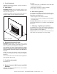
14 Appliance Setup A. Remove Glass Assembly F. Lava Rock Placement See Section 14.I. 1. Add lava rock to lava rock basket. See Figure 14.2. B. Remove the Shipping Materials Remove shipping materials from inside or underneath the firebox. C. Clean the Appliance Clean/vacuum any sawdust that may have accumulated inside the firebox or underneath in the control cavity. LAVA ROCK BASKET D. Accessories Install approved accessories per instructions included with accessories.
G. Ember Placement WARNING! Risk of Explosion! Follow ember placement instructions in manual. DO NOT completely block burner ports with ember material. Replace ember material annually. Improperly placed embers interfere with proper burner operation. Ember material is shipped with this gas appliance. To place the ember material: • Embers CANNOT completely block burner ports. Care should be taken not to block the lighting trail of ports. • Embers may only be placed in areas as shown in Figure 14.3.
H. Install the Log Assembly FIBER BURNER TOP Log Assembly: LOGS-BV36 LOCATING HOLES TAB BENT IN = NG BURNER SHIELD LOG PLACEMENT TABS PILOT COVER BURNER ASSEMBLY LOG PLACEMENT INDENTATIONS TAB NOT BENT = LP GRATE TINE Figure 2. Log Placement Tabs GUIDE SLEEVES Figure 1 CAUTION: Logs are fragile, handle with care. Log #1 (SRV2209-701): Locate log placement tabs on the pilot cover (see Figure 2). Locate the log placements slots on the bottom of Log # 1 (see Figure 3).
LOG NOSE RIGHT GRATE TINE 1 2 1 2 3 3 4 Figure 8 Figure 7 Log #3 (SRV2209-703): Mate the slot located on the bottom of Log #3 with the right log placement tab on top of Log #1. After slot and tab have been fitted together, mate the groove located on the bottom of Log #3 with the horizontal grate bar and slide Log # 3 toward the right until it rests against the far right grate tine (see Figure 7). Log #4 (SRV2164-704): Place Log #4 in the left log indentation on the burner top (see Figure 2).
Log Assembly: LOGS-BV42 H. Install the Log Assembly FIBER BURNER TOP LOCATING HOLES LOG PLACEMENT INDENTATIONS TAB BENT IN = NG LOG PLACEMENT TABS BURNER SHIELD PILOT COVER BURNER ASSEMBLY TAB NOT BENT = LP GRATE TINE Figure 2. Log Placement Tabs GUIDE SLEEVES Figure 1 CAUTION: Logs are fragile, handle with care. Log #1 (SRV2212-701): Locate log placement tabs on the pilot cover (see Figure 2). Locate the log placements slots on the bottom of Log # 1 (see Figure 3).
RIGHT GRATE TINE 1 2 3 3 4 HORIZONTAL GRATE BAR Figure 8 Figure 7 1 2 LOG #4 CONTACTS LOG #2 Log #3 (SRV2212-703): Mate the slot located on the bottom of Log #3 with the right log placement tab on top of Log #1. After slot and tab have been fitted together, mate the groove located on the bottom of Log #3 with the horizontal grate bar and far right grate tine. Log # 3 will sit down on top of both the grate tine and the horizontal grate bar (see Figure 7).
I. Fixed Glass Assembly K. Air Shutter Setting WARNING! Risk of Asphyxiation! Handle fixed glass assembly with care. Inspect the gasket to ensure it is undamaged and inspect the glass for cracks, chips or scratches. Air shutter settings should be adjusted by a qualified service technician at the time of installation. The air shutter is set at the factory for minimum vertical vent run. Adjust air shutter for longer vertical runs. See Figure 14.6. • DO NOT strike, slam or scratch glass.
15 Troubleshooting With proper installation, operation, and maintenance your gas appliance will provide years of trouble-free service. If you do experience a problem, this troubleshooting guide will assist a qualified service technician in the diagnosis of a problem and the corrective action to be taken. This troubleshooting guide can only be used by a qualified service technician. Contact your dealer to arrange a service call by a qualified service technician. A.
IntelliFire Plus™ Ignition System - (continued) Symptom 4. Pilot lights but continues to spark, and main burner will not ignite. (If the pilot continues to spark after the pilot flame has been lit, flame rectification has not occurred.) Possible Cause A. A shorted or loose connection in flame sensing rod. Corrective Action Verify all connections to wiring diagram in manual. Verify connections underneath pilot assembly are tight.
16 Reference Materials A. Appliance Dimension Diagram Dimensions are actual appliance dimensions. Use for reference only. For framing dimensions and clearances refer to Section 5.
I J G H K N D C L E O B A M F Location Inches Millimeters Location Inches Millimeters A 48 1219 I 35-1/2 902 B 43 1092 J 17-3/4 451 C 35-1/2 902 K 5 127 D 36-9/16 929 L 2-5/8 143 E 2-3/8 60 M 8-7/8 225 F 5-1/4 133 N 42-7/8 1089 G 21-1/16 535 O 1 25 H 9-1/2 241 Figure 16.2 BV4842DBI Appliance Dimensions E D C See your Hearth & Home Technologies dealer for a complete listing of optional components. B A Catalog # LDS-BV A B C E E in.
BV4236DBI Service Parts B. Service Parts Beginning Manufacturing Date: Dec 2009 Ending Manufacturing Date: Active 36” Gas Fireplace - BV Log Set Assembly 2 1 4 6 5 7 3 8 15 16 13 14 9 10 9.1 11 12 9.2 18 17 IMPORTANT: THIS IS DATED INFORMATION. When requesting service or replacement parts for your appliance please provide model number and serial number. All parts listed in this manual may be ordered from an authorized dealer.
BV4842DBI Service Parts Beginning Manufacturing Date: Dec 2009 Ending Manufacturing Date: Active 42” Gas Fireplace- BV Log Set Assembly 2 1 4 6 5 7 3 10 15 14 13 8 9 9.1 11 12 16 9.2 18 17 IMPORTANT: THIS IS DATED INFORMATION. When requesting service or replacement parts for your appliance please provide model number and serial number. All parts listed in this manual may be ordered from an authorized dealer.
BV4236DBI , BV4842DBI Service Parts Beginning Manufacturing Date: Dec 2009 Ending Manufacturing Date: Active #19 Valve Assembly 19.1 19.2 19.13 19.3 19.14 19.15 19.4 19.5 19.12 19.6 19.7 19.9 19.8 19.10 19.11 IMPORTANT: THIS IS DATED INFORMATION. When requesting service or replacement parts for your appliance please provide model number and serial number. All parts listed in this manual may be ordered from an authorized dealer. ITEM 19.1 19.
Service Parts BV4236DBI , BV4842DBI Beginning Manufacturing Date: Dec 2009 Ending Manufacturing Date: Active IMPORTANT: THIS IS DATED INFORMATION. When requesting service or replacement parts for your appliance please provide model number and serial number. All parts listed in this manual may be ordered from an authorized dealer.
C. Contact Information Hearth & Home Technologies Inc. 7571 215th Street West, Lakeville, MN 55044 www.hearthnhome.com Please contact your Hearth & Home Technologies dealer with any questions or concerns. For the location of your nearest Hearth & Home Technologies dealer, please visit www.hearthnhome.com.