Owner’s Manual Installation and Operation Model(s): NDV3630, NDV3933, NDV4236, NDV4842, NDV3630I, NDV3933I, NDV4236I, NDV4842I, NDV3630L, NDV3933L, NDV4236L, NDV4842L, NDV3630IL, NDV3933IL, NDV4236IL, NDV4842IL NOTICE DO NOT DISCARD THIS MANUAL • Important operating and maintenance instructions included. • Read, understand and follow these instructions for safe installation and operation.
Read this manual before installing or operating this appliance. Please retain this owner’s manual for future reference. A. Congratulations This Owner’s Manual should be retained for future reference. We suggest that you keep it with your other important documents and product manuals. Congratulations on selecting a Heatilator gas fireplace, an elegant and clean alternative to wood burning fireplaces.
Safety Alert Key: • • • • DANGER! Indicates a hazardous situation which, if not avoided will result in death or serious injury. WARNING! Indicates a hazardous situation which, if not avoided could result in death or serious injury. CAUTION! Indicates a hazardous situation which, if not avoided, could result in minor or moderate injury. NOTICE: Used to address practices not related to personal injury. Table of Contents A. Congratulations B.
15 Appliance Setup A. B. C. D. E. F. G. H. I. J. K. L. M. N. O. P. Remove the Packaging Remove Screen Package Assembly Remove the Shipping Materials Removing Fixed Glass Assembly Clean the Appliance Accessories Place the Rockwool Place the Lava Rock Place the Vermiculite Replacing Fixed Glass Assembly Air Shutter Setting Remove Screen Protector Unpackage the Hood & Floor Cover Install Hood Install Floor Cover Close the Screen Assembly 55 55 55 55 55 55 56 56 56 56 56 57 57 57 57 58 16 Troubleshooting A.
B. Limited Lifetime Warranty Hearth & Home Technologies Inc. LIMITED LIFETIME WARRANTY Hearth & Home Technologies Inc., on behalf of its hearth brands (”HHT”), extends the following warranty for HHT gas, wood, pellet, coal and electric hearth appliances that are purchased from an HHT authorized dealer.
B.
1 Listing and Code Approvals A. Appliance Certification C. BTU Specifications Novus NDV MODELS: NDV3630, NDV3933, NDV4236 and NDV3630 NDV3933 Standing Pilot or IPI NDV4842 Series Max/Min Input Rate (NG) LABORATORY: Underwriters Laboratories, Inc. (UL) TYPE: Vented Gas Fireplace Heaters STANDARD: ANSI Z21.88b-2008/CSA 2.33b-2008 NOTICE: This installation must conform with local codes or, in the absence of local codes, with the National Fuel Gas Code, ANSI Z223.
Note: The following requirements reference various Massachusetts and national codes not contained in this document. H.
User Guide 2 Operating Instructions • Install a switch lock or a wall/remote control with child protection lockout feature. • Keep remote controls out of reach of children. • Never leave children alone near a hot fireplace, whether operating or cooling down. • Teach children to NEVER touch the fireplace. • Consider not using the fireplace when children will be present. Contact your dealer for more information, or visit: www. hpba.org/safety-information. A.
C. Fan Kit (optional) F. Fixed Glass Assembly • See Section 15. Refer to Figure 2.1 for location of control. D. Clear Space WARNING! DO NOT place combustible objects in front of the fireplace or block louvers. High temperatures may start a fire. See Figure 2.2. Avoid placing candles and other heat-sensitive objects on mantel or hearth. Heat may damage these objects. G.
I. Lighting Instructions (IPI) • • • For normal use, activate/deactivate your fireplace with the wall switch or remote control. The IPI system may be operated with two D-cell batteries. When using batteries, unplug the transformer. To prolong battery life, remove them when using the transformer. If your fireplace must be deactivated for service or an extended period of time, follow the instructions below.
J. Lighting Instructions (Standing Pilot) • • For normal use, activate/deactivate your fireplace with the wall switch or remote control. If your fireplace must be deactivated for service or an extended period of time, follow the instructions below. LIGHTING INSTRUCTIONS FOR YOUR SAFETY READ BEFORE LIGHTING 1. Open control access panel. WARNING: If you do not follow these instructions exactly, a fire or explosion may result causing property damage, personal injury or loss of life. A.
K. After Appliance is Lit Initial Break-in Procedure Indicator • The appliance should be run three to four hours continuously on high. • Turn the appliance off and allow it to completely cool. • Remove and clean fixed glass assembly. See Section 3. • Replace the fixed glass assembly and run continuously on high an additional 12 hours. This cures the materials used to manufacture the fireplace. NOTICE! Open windows for air circulation during appliance break-in.
3 Maintenance and Service Any safety screen or guard removed for servicing must be replaced prior to operating the appliance. When properly maintained, your appliance will give you many years of trouble-free service. We recommend annual service by a qualified technician. A. Maintenance Tasks-Homeowner Installation and repair should be done by a qualified technician only. The appliance should be inspected before use and at least annually by a professional service person.
Tools needed: Protective gloves, vacuum cleaner, dust cloths Venting Frequency: Seasonally • By: Homeowner Tools needed: Protective gloves and safety glasses. • • • • • Inspect venting and termination cap for blockage or obstruction such plants, bird nests, leaves, snow, debris, etc. Verify termination cap clearance to subsequent construction (building additions, decks, fences, or sheds). See Section 6. Inspect for corrosion or separation. Verify weather stripping, sealing and flashing remains intact.
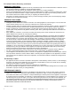
IC F CI T C U E P S D O R (Either cobrahead or SIT) P Figure 3.1 IPI Flame Patterns Figure 3.2 Standing Pilot Flame Patterns 16 Heatilator • Novus NDV Series • 4055-187 Rev.
4 Getting Started Installer Guide A. Typical Appliance System NOTICE: Illustrations and photos reflect typical installations and are for design purposes only. Illustrations/diagrams are not drawn to scale. Actual product may vary from pictures in manual VERTICAL TERMINATION CAP (SECTION 10) NOTE: An installation will have either a vertical termination or a horizontal termination. It will not have both (as shown).
B. Design and Installation Considerations D. Inspect Appliance and Components Heatilator direct vent gas appliances are designed to operate with all combustion air siphoned from outside of the building and all exhaust gases expelled to the outside. No additional outside air source is required. • Installation MUST comply with local, regional, state and national codes and regulations.
5 Framing and Clearances NOTICE: Illustrations reflect typical installations and are FOR DESIGN PURPOSES ONLY. Illustrations/diagrams are not drawn to scale. Actual installation may vary due to individual design preference. A. Select Appliance Location When selecting a location for your appliance it is important to consider the required clearances to walls (see Figure 5.1). WARNING! Risk of Fire or Burns! Provide adequate clearance around air openings and for service access.
To further prevent drafts, the wall shield and ceiling firestops should be caulked with caulk with a minimum of 300ºF continuous exposure rating to seal gaps. Gas line holes and other openings should be caulked with caulk with a minimum of 300ºF continuous exposure rating or stuffed with unfaced insulation. If the appliance is being installed on a cement slab, a layer of plywood may be placed underneath to prevent conducting cold up into the room. B.
Mantel Legs or Wall Projections D. Mantel and Wall Projections WARNING! Risk of Fire! Comply with all minimum clearances to combustibles as specified. Framing or finishing material closer than the minimums listed must be constructed entirely of non-combustible materials (i.e., steel studs, concrete board, etc). Top of Appliance Drywall A Mantels B 30 in.
6 Termination Locations A. Vent Termination Minimum Clearances WARNING A B 6 in. (minimum) up to 20 in. 152 mm/508 mm 18 in. minimum 457 mm 20 in. and over 0 in. minimum Fire Risk. Maintain vent clearance to combustibles as specified. • DO NOT pack air space with insulation or other materials. Failure to keep insulation or other materials away from vent pipe may cause fire. Gas, Wood or Fuel Oil Termination Cap B A* Horizontal overhang 24 in. min.
H D O E N V L V C B Fixed Closed V F B Openable Fixed Closed V V V G V B B B V J X M V I A V TERMINATION CAP K X V A GAS METER X AIR SUPPLY INLET Measure vertical clearances from this surface Q RESTRICTION ZONE (TERMINATION NOT ALLOWED) V P W V R U V T Electrical Service U V D* S V Measure horizontal clearances from this surface. Covered Alcove Applications Dimension Descriptions A Clearance above the ground, a veranda, porch, deck or balcony - 12 in. (30 cm) minimum.
7 Vent Information and Diagrams A. Approved Pipe D. Measuring Standards This appliance is approved for use with Hearth & Home Technologies DVP and SLP venting systems. Refer to Section 17.B for vent component information. Vertical and horizontal measurements listed in the vent diagrams were made using the following standards. DO NOT mix pipe, fittings or joining methods from different manufacturers. The pipe is tested to be run inside an enclosed wall.
E. Vent Diagrams To replace the first starter elbow with two 45° elbows, refer to Figure 7.4. All other 90° elbows can be replaced with two 45° elbows. General Rules: • • • • • • • SUBTRACT 3 ft. from the total H measurement for each 90° elbow installed horizontally. SUBTRACT 1-1/2 ft. from the total H measurement for each 45° elbow installed horizontally. A maximum of three 90° elbows (or six 45° elbows) may be used in any vent configuration. Some elbows may be installed horizontally.
1. Top Vent - Horizontal Termination - (continued) One Elbow V1 V1 Min V1 Max H1 Max. 0* - 24 in./635 mm 4 in./102 mm - 4 ft/1.22 m 6 in./152 mm - 6 ft/1.83 m 12 in./305 mm - 11 ft/3.35 m 18 in./457 mm - 18 ft/5.49 m 24 in./610 mm - 25 ft/7.62 m - 25 ft/7.62 m (DVP) 25 ft/7.62 m - 23 ft/7.62 m (SLP) 25 ft/7.62 m H1 * You may install the elbow directly on top of the appliance (DVP only). Figure 7.
1. Top Vent - Horizontal Termination - (continued) V1 min. Three Elbows V1+V2 max. H1+H2 max. 12 in./305 mm 24 ft/7.32 m (DVP) 19 ft/5.79 m 12 in./305 mm 22 ft/6.71 m (SLP) 19 ft/5.79 m Installed Vertically H2 V2 V1 H1 Figure 7.6 Heatilator • Novus NDV Series • 4055-187 Rev.
2. Top Vent - Vertical Termination Install Top Vent Flue Visor - No Elbow Configurations No Elbow • • • 12 ft (3.66 m) min. 60 ft (18.29 m) max. Figure 7.7a Remove screws holding flue visor to firebox top. See Figure 7.7b. Remove the flue visor. Using the screws removed and the same holes, install the top vent flue baffle and flue visor. - The flue visor will be turned to install below the level of the firebox top for 12-30 ft vertical runs of vent. See Figure 7.7c.
2. Top Vent - Vertical Termination - (continued) Note: Subtract 3 ft (914 mm) from the total horizontal measurement for each 90° elbow installed horizontally. Subtract 1-1/2 ft (457 mm) from the total horizontal measurement for each 45° elbow installed horizontally. Three Elbows Maximum horizontal run is 100% of vertical, but cannot exceed 26 ft (7.92 m) 12 ft (3.66 m) min. 60 ft (18.29 m) max. Figure 7.9 Heatilator • Novus NDV Series • 4055-187 Rev.
3. Rear Vent - Horizontal Termination (DVP only) No Elbow 18 in. (457 mm) max. Figure 7.10 One 45° Elbow 18 in. (457 mm) max. Figure 7.11 30 Heatilator • Novus NDV Series • 4055-187 Rev.
3. Rear Vent - Horizontal Termination (DVP only) - (continued) Two Elbows Model H1 Max NDV Series Total Vert Total Horiz V Min. H1 + H 2 ft 0-2 1 3 m 0-.61 0.31 0.91 ft 4 2 6 m 1.22 0.61 1.83 ft 6 3 9 m 1.83 0.91 2.74 ft 8 4 12 m 2.44 1.22 3.66 ft 8 5 15 m 2.44 1.52 4.57 ft 8 6 18 m 2.44 1.83 5.49 V1 H2 H1 Figure 7.12 Three Elbows Model Note: Subtract 3 ft (914 mm) from the total horizontal measurement for each 90° elbow installed horizontally.
4. Rear Vent - Vertical Termination (DVP only) One Elbow 0 min. 6 ft (1.83 m) max. 12 ft (3.66 m) min. 60 ft (18.29 m) max. Figure 7.14 Note: Subtract 3 ft (914 mm) from the total horizontal measurement for each 90° elbow installed horizontally. Subtract 1-1/2 ft (457 mm) from the total horizontal measurement for each 45° elbow installed horizontally. Two Elbows 12 ft (3.66 m) min. 60 ft (18.29 m) max. 0 min. 6 ft (1.83 m) max. Maximum horizontal run is 100% of vertical, but cannot exceed 26 ft (7.
4. Rear Vent - Vertical Termination (DVP only) - (continued) Three Elbows 0 min. 6 ft (1.83 m) max. 12 ft (3.66 m) min. 60 ft (18.29 m) max. Maximum horizontal run is 100% of vertical, but cannot exceed 26 ft (7.92 m). Figure 7.16 Heatilator • Novus NDV Series • 4055-187 Rev.
8 Vent Clearances and Framing A. Pipe Clearances to Combustibles B. Wall Penetration Framing WARNING! Risk of Fire! Maintain air space clearance to vent. DO NOT pack insulation or other combustibles: Combustible Wall Penetration • • • Between ceiling firestops Between wall shield firestops Around vent system Failure to keep insulation or other material away from vent pipe may cause over heating and fire. Note: Heat shields MUST overlap by a minimum of 1-1/2 in. (38 mm).
C. Install the Ceiling Firestop A ceiling firestop MUST be used between floors and attics. • DVP Pipe only - Frame an opening 10 in. by 10 in. (254 mm by 254 mm) whenever the vent penetrates a ceiling/floor (see Figure 8.3). • SLP Pipe only - Frame an opening 9 in. by 9 in. (229 mm x 229 mm) whenever the vent penetrates a ceiling/floor (see Figure 8.3). • Frame the area with the same sized lumber as used in ceiling/floor joist.
D. Install Attic Insulation Shield WARNING! Fire Risk. DO NOT allow loose materials or insulation to touch vent. Hearth & Home Technologies Inc. requires the use of an attic shield. The National Fuel Gas Code ANSI Z223.1 requires an attic shield constructed of 26 gauge minimum metal that extends at least 2 in. (51 mm) above insulation. Attic shields must meet specified clearance and be secured in place. Flat Ceiling Installation • Remove one shield from box.
9 Appliance Preparation • A. Top Vent Cut the metal retaining band and fold the sides out. CAUTION! Risk of Cuts/Abrasions/Flying Debris. Wear protective gloves and safety glasses during installation. Sheet metal edges are sharp. NOTICE: Once appliance is set up for top or rear venting, it CANNOT be changed at a later time. Figure 9.4 • Fold the center parts of the retaining band up and use to remove the vent cap. Figure 9.
B. Rear Vent NOTICE: Once appliance is set up for top or rear venting, it CANNOT be changed at a later time. NOTICE: Once the vent cap has been removed it CANNOT be reattached. Figure 9.7 • Fold the tabs toward the center of the fire plug (90º) and remove the insulation gasket. Figure 9.10 • Discard the vent cap, remove and discard the insulation basket. Figure 9.8 • Cut the metal retaining band and fold the sides out. Figure 9.11 • Attach the first vent section (it will snap into place).
C. Secure and Level the Appliance WARNING! Risk of Fire! Prevent contact with: • • • Sagging or loose insulation Insulation backing or plastic Framing and other combustible materials Block openings into the chase to prevent entry of blownin insulation. Make sure insulation and other materials are secured. DO NOT notch the framing around the appliance standoffs. Failure to maintain air space clearance may cause overheating and fire.
10 Installing Vent Pipe A. Assemble Vent Sections (DVP only) Attach Vent to the Firebox Assembly Note: The end of the pipe sections with the lanced tabs will face toward the appliance. Attach the first pipe section to the starting collar: • • • • Lanced pipe end of the starting collar Inner pipe over inner collar Push the pipe section until all lanced tabs snap in place Lightly tug on pipe to confirm it has locked.
B. Assemble Vent Sections (SLP Pipe Only) To attach the first vent component to the starting collars of the appliance • • • • • • Attach an DVP-SLP24 adapter to the starting collar of the appliance. Lock the vent components into place by sliding the pipe section onto the collar. Align the seam of the pipe and seam of collar to allow engagement. Rotate the vent component to lock into place. Use this procedure for all vent components. See Figure 10.5.
D. Secure the Vent Sections E. Disassemble Vent Sections • • Vertical runs of DVP pipe must be supported every 8 ft. (2.44 m) after the 25 ft. (7.62 m) maximum unsupported rise. Vertical runs of SLP pipe must be supported every 8 ft. (2.44 m). Horizontal sections of vent must be supported every 5 ft. (1.52 m) with a vent support or plumber’s strap. Wall shield firestops may be used to provide horizontal support. Vent support or plumber’s strap (spaced 120° apart) may be used for support. See Figures 10.
F. Install Decorative Ceiling Components (SLP only) Level A decorative ceiling thimble can be installed on a flat ceiling through which the vent passes. The ceiling thimble is used to cover the firestop, which is installed according to section 8.C. Cathedral ceiling support box • Seal the gap between the vent pipe and firestop using high temperature silicone (300º F minimum continuous exposure rating) to prevent cold air infiltration.
G. Install Metal Roof Flashing • H. Assemble and Install Storm Collar See minimum vent heights for various pitched roofs (Figure 10.14) to determine the length of pipe to extend through the roof. Slide the roof flashing over the pipe sections extending through the roof as shown in Figure 10.15. • Horizontal overhang 24 in. min. (610 mm) Termination Cap 20 in. (508 mm) CAUTION! Risk of Cuts/Abrasions/Flying Debris. Wear protective gloves and safety glasses during installation.
I. Install Vertical Termination Cap • • Attach the vertical termination cap by sliding the inner collar of the cap into the inner flue of the pipe section while placing the outer collar of the cap over the outer flue of the pipe section. Secure the cap by driving three self-tapping screws (supplied) through the pilot holes in the outer collar of the cap into the outer flue of the pipe (see Figure 10.18). K.
Install Horizontal Termination Cap WARNING! Risk of Fire! The telescoping flue section of the termination cap MUST be used when connecting vent. • 1-1/2 (38 mm) minimum overlap of flue telescoping section is required. • Failure to maintain overlap may cause overheating and fire. CAUTION! Risk of Burns! Local codes may require installation of a cap shield to prevent anything or anyone from touching the hot cap. • • Vent termination must not be recessed in the wall.
11 Shrouds A. HHT Shrouds • You may install a shroud with this fireplace. See Section 17.D. for a list of UL Listed shrouds. Follow the instructions included with these optional components B. Field Constructed Shrouds WARNING! Risk of Fire! Shrouds must be constructed as specified. Improper construction may overheat chase top. • Chase top shrouds may be field constructed where permitted by regional building codes. NOTICE: Some regional codes require an agency-Listed shroud.
Mailbox Style Shroud (may be used with DVP-TV, DVP-TVHW, SLP-TVHW) Min. Base Dims. Min. Height in 20 x 20 mm 508 x 508 Min. Height Min. Base Dim in 18 mm 457 Min. Base Dim Figure 11.2 Mailbox Style Shroud Dimensions Roofed Style Shroud (may be used with DVP-TV, DVP-TVHW, SLP-TVHW) Min. Base Dims. in 20 x 20 mm Minimum Height Min. Opening Width Minimum Opening Height Minimum Base Dimension Min. Base Dime nsion Figure 11.2 Roofed Style Shroud Dimensions 48 508 x 508 Min.
12 Gas Information A. Fuel Conversion C. Gas Connection • • • Make sure the appliance is compatible with available gas types. Conversions must be made by a qualified technician using Hearth & Home Technologies specified and approved parts. • • B. Gas Pressure • • • Optimum appliance performance requires proper input pressures. Gas line sizing requirements will be determined in ANSI Z221.3 National Fuel Gas Code in the USA and CAN/ CGA B149 in Canada.
13 Electrical Information A. Wiring Requirements B. Standing Pilot Ignition System Wiring NOTICE: This appliance must be electrically wired and grounded in accordance with local codes or, in the absence of local codes, with National Electric Code ANSI/NFPA 70-latest edition or the Canadian Electric Code CSA C22.1. • Wire the appliance junction box to 110-120 VAC. This is required for use of optional accessories (standing pilot ignition) or proper operation of the appliance (Intellifire ignition).
E. Electrical Service and Repair WARNING! Risk of Shock! Label all wires prior to disconnection when servicing controls. Wiring errors can cause improper and dangerous operation. Verify proper operation after servicing. WARNING! Risk of Shock! Replace damaged wire with type 105° C rated wire. Wire must have high temperature insulation. STANDING PILOT BRN RED VALVE ON/OFF PIGGYBACK WIRE WHT THERMOSTAT WIRE ASSEMBLY / WALL SWITCH WIRE RED Figure 13.
F. Junction Box Installation If the box is being wired from the OUTSIDE of the appliance: Romex Connector • Remove the cover plate located on the outer shell - right side (see Figure 13.4). • Install the supplied Romex™ connector in the cover plate. If the box is being wired from the INSIDE of the appliance: • Cover Plate outside firebox Remove the screw attaching the junction box/receptacle to the outer shell, rotate the junction box inward to disengage it from the outer shell (see Figure 13.4).
14 Finishing A. Mantel and Wall Projections WARNING! Risk of Fire! Comply with all minimum clearances to combustibles as specified. Framing closer than the minimums listed must be constructed entirely of non-combustible materials (i.e., steel studs, concrete board, etc.) Failure to comply could cause fire. Mantels 30 in.
B. Facing Material • Cover the metal front faces with non-combustible materials only. Facing and/or finishing materials must not interfere with air flow through louvers, operation of louvers or doors, or access for service. Facing and/or finishing materials must never overhang into the glass opening. Observe all clearances when applying combustible materials. Seal joints between the finished wall and appliance top and sides using a 300 °F minimum sealant. Refer to Figure 14.3.
15 Appliance Setup A. Remove the Packaging C. Remove the Shipping Materials Remove the shrink film, corrugated top cap, bottom cap and column protectors from the appliance. The appliance should look as shown in Figure 15.1. Remove the shipping materials from inside or underneath the firebox. D. Removing Fixed Glass Assembly WARNING! Risk of Asphyxiation! Handle fixed glass assembly with care. Inspect the gasket to ensure it is undamaged and inspect the glass for cracks, chips or scratches.
G. Place the Rockwool K. Air Shutter Setting WARNING! Risk of Explosion! Follow rockwool placement instructions. DO NOT place rockwool directly over burner ports. Replace rockwool material annually. Improperly placed rockwool interferes with proper burner operation. • • Rockwool is shipped with this gas appliance. Place a small amount of 1/2 in. diameter pieces (dimesize) rockwool on the burner pan so that the rockwool touches, but does not cover, the holes in the burner pan (refer to Figure 15.4).
L. Remove Screen Protector N. Install Hood • • • Cut the tape on top of the screen protector. See Figure 15.7. Open the screen protector and remove the screen. See Figure 15.8. • • Locate the four screws just inside the upper section of the appliance. Slide the hood into position uncer the screw heads. Tighten the four screws. See Figure 15.10. Figure 15.7 Cut Packaging Tape Figure 15.10 Intalling Hood O. Install Floor Cover Install the floor cover as shown in Figure 15.11. Figure 15.
P. Close the Screen Assembly • Make sure the screen magnetic touch latches are in the open position. See Figure 15.12. Hange the screen on the shoulder screws in the columns. See Figure 15.13. • • • Rotate the screen in at the bottom until it touches the magnetic touch latches. See Figure 15.14. Press in on the bottom of the screen until the magnetic touch latches close. See Figure 15.15. Open Figure 15.14 Rotate the Screen Down Figure 15.
16 Troubleshooting With proper installation, operation, and maintenance your gas appliance will provide years of trouble-free service. If you do experience a problem, this troubleshooting guide will assist a qualified technician in the diagnosis of a problem and the corrective action to be taken. This troubleshooting guide can only be used by a qualified technician. Contact your dealer to arrange a service call by a qualified technician. A. Standing Pilot Ignition System Symptom 1.
Troubleshooting (continued) Symptom 3. (Continued) 4. Frequent pilot outage problem. Possible Cause Corrective Action C. Failed valve. Turn the valve knob to the ON position. Place the ON/OFF switch in the ON position. Check the millivolt meter a the thermopile terminals. The millivolt meter should read greater than 125mV. If the reading is acceptable, and if the burner does not come on, replace the gas valve. D. Plugged burner orifice. Check the burner orifice for stoppage. Remove stoppage. E.
B. Intellifire Ignition System Symptom 1. Pilot won’t light. The ignitor/module makes noise, but no spark. Possible Cause A. Incorrect wiring. Corrective Action Verify “S” wire (white) for sensor and “I” wire (orange) for ignitor are connected to correct terminals on module and pilot assembly. B. Loose connections or electrical Verify no loose connections or electrical shorts in wiring from shorts in the wiring. module to pilot assembly.
Intellifire Ignition System - (continued) Symptom Possible Cause 4. Pilot lights but continues A. A shorted or loose connection in flame sensing rod. to spark, and main burner will not ignite. (If the pilot continues to spark after the pilot flame has been lit, flame rectification has not B. Poor flame rectification or occurred.) contaminated flame sensing rod. 62 Corrective Action Verify all connections to wiring diagram in manual. Verify connections underneath pilot assembly are tight.
17 Reference Materials A. Appliance Dimension Diagram Dimensions are actual appliance dimensions. Use for reference only. For framing dimensions and clearances refer to Section 3. C 19-1/8 in. (486 mm) 11-5/8in. (295 mm) A Alternative Gas Access Gas Line Access 31-1/2 in. (800 mm) 34 in. (864 mm) 6-1/2 in. (165 mm) 2-3/8 in. (60 mm) Electrical Access 34-1/2 in. (876 mm) B 3 in. (76 mm) 1-1/2 in. (38 mm) 1-3/4 in. (44 mm) 8 in. (203 mm) 15-3/4 in. (400 mm) 23-1/2 in.
B. Vent Components Diagrams Effective Height/Length mm Pipe inches DVP4 DVP6 DVP12 DVP24 DVP36 DVP48 DVP6A DVP12A Effective Height/Length 4 6 12 24 36 48 3-6 3 - 12 4-7/8 in. (124 mm) 102 152 305 610 914 1219 76 - 152 76 - 305 10-1/2 in. (267 mm) 45° 10-7/8 in. (276 mm) DVP45 45° Elbow DVP Pipe (see chart) 10 in. (254 mm) 11-3/8 in. (289 mm) 1 in. (25 mm) 7-3/8 in. (187 mm) 9-1/4 in. (235 mm) 13-1/4 in. (337 mm) Assembled Height: 24 in./610 mm Diameter: 10 in.
B. Vent Components Diagrams (continued) 31 in. (787 mm) 24-5/8 in. (625 mm) 13-1/4 in. (367 mm) 27-1/2 in. (698 mm) 24-5/8 in. (625 mm) 13-1/4 in. (367 mm) RF12M Roof Flashing Multi-pak RF6M Roof Flashing Multi-pak 5 in. (127 mm) 13-3/4 in. (349 mm) 5 in. (127 mm) 11-7/8 in. (302 mm) 13-7/8 in. (352 mm) 13-3/4 in. (349 mm) BEK Trap Cap Brick Extension DVP-BEK2 DVP-HPC Cap Brick Extension 11-5/8 in. (295 mm) 12-1/8 in. (308 mm) 7-1/8 in. (181 mm) 5-3/4 in.
B. Vent Components Diagrams (continued) 7-3/8 in. (187 mm) 1-1/2 in. (38 mm) 9 in. (229 mm) 2-3/4 in. (70 mm) 12-1/2 in. (317 mm) 11-1/2 in. (280 mm) 17-3/4 in. (451 mm) 14 in. (356 mm) 12-1/4 in. (311 mm) 16 in. (406 mm) PVK-80 (For use with IPI and DSI appliances only.) 12 in. (305 mm) 3-7/8 in. (98 mm) DVP-TB1 Basement Vent Cap 10-1/2 in. (267 mm) DVP-TV Vertical Termination Cap 7-1/4 in. (184 mm) 12-1/2 in. (318 mm) 5-1/4 in.
B. Vent Components Diagrams (continued) Note: Heat shields MUST overlap by a minimum of 1-1/2 in. (38 mm). The heat shield is designed to be used on a wall 4 in. to 7-1/4 in. (102 mm to 184 mm) thick. If wall thickness is less than 4 in. (102 mm) the existing heat shields must be field trimmed. If wall thickness is greater than 7-1/4 in. (184 mm) a DVP-HSM-B will be required. 8 in. (203 mm) Heat Shield 15-1/8 in. (384 mm) Term Cap Minimum Effective Length Maximum Effective Length 3-1/8 in. 4-5/8 in.
B. Vent Components Diagrams (continued) Optional Wire Harness 13-5/8 IN. 346 mm DESCRIPTION 12-1/2 IN. 318 mm PART NUMBER 10 ft. PV Wire Harness PVI-WH10 20 ft. PV Wire Harness PVI-WH20 40 ft. PV Wire Harness PVI-WH40 60 ft. PV Wire Harness PVI-WH60 80 ft. PV Wire Harness PVI-WH80 100 ft. PV Wire Harness PVI-WH100 Note: Wire harnesses required to power the PVI-SLP connect to the appliance and are ordered separately from PVI-SLP. Contact your dealer to order. 20-3/4 IN.
B. Vent Components Diagrams (continued) 6-1/2 in. 165 mm 6-1/2 in. 165 mm 8-3/4 in. 222 mm 6-1/2 in. 165 mm 9-1/4 in. 235 mm 6 in. 152 mm 6-5/8 in. 168 mm SLP45 45° Elbow 6-5/8 in. 168 mm 9-7/8 in. 251 mm SLP90-ST - 90° Elbow Effective Height/ Length 6-1/2 in. 165 mm Effective Height/Length SLP PIPE 10-7/8 in. 276 mm Pipe inches mm 102 SLP4 4 SLP6 6 152 SLP12 12 305 SLP24 24 610 SLP36 36 914 SLP48 48 1219 SLP6A 2-6 51 - 152 SLP12A 2 - 12 51 - 305 25-3/16 in.
B. Vent Components Diagrams (continued) 13 in. 330 mm 14 in. 356 mm 1-5/16 in. 34 mm 13 in. 330 mm 10-9/16 in. 269 mm SLP-DCF-BK Ceiling Firestop Black SLP-CCS-BK Cathedral Ceiling Support Box-Black 26 in. 660 mm 12 in. 305 mm DVP-HSM-B Extended Heat Shield 12-1/2 in. 318 mm 14-7/16 in. 367 mm 8-1/16 in. 205 mm 2-5/16 in. 59 mm 14-7/16 in. 367 mm SLP-TVHW Vertical Termination Cap SLP-WT-BK Wall Thimble-Black 10-11/16 in. 271mm 28-1/2 in. 724 mm 1 in. (25 mm) 7-1/4 in. (184 mm) 14 in.
B. Vent Components Diagrams (continued) Note: Heat shields MUST overlap by a minimum of 1-1/2 in. (38 mm). The heat shield is designed to be used on a wall 4 in. to 7-1/4 in. (102 mm to 184 mm) thick. If wall thickness is less than 4 in. (102 mm) the existing heat shields must be field trimmed. If wall thickness is greater than 7-1/4 in. (184 mm) a DVP-HSM-B will be required. 8 in. (203 mm) Heat Shield 15-1/8 in. (384 mm) Term Cap Minimum Effective Length Maximum Effective Length 3 1/8 in. 4 3/4 in.
NDV3630, NDV3630i C. Service Parts Beginning Manufacturing Date: Feb 2008 Ending Manufacturing Date: Active 30 in. Novus Circulating - DV 5 6 10 9 12 8 7 28 11 27 13 26 14 25 24 15 16 23 22 21 17 18 19 20 Log Set Assembly 3 1 2 Part number list on following page. 72 Heatilator • Novus NDV Series • 4055-187 Rev.
NDV3630, NDV3630i C. Service Parts (continued) IMPORTANT: THIS IS DATED INFORMATION. When requesting service or replacement parts for your appliance please provide model number and serial number. All parts listed in this manual may be ordered from an authorized dealer.
NDV3933, NDV3933i C. Service Parts (continued) Beginning Manufacturing Date: Feb 2008 Ending Manufacturing Date: Active 33 in. Novus Circulating - DV 5 6 10 9 12 8 7 28 11 27 13 26 14 25 24 15 22 16 23 21 17 18 19 Log Set Assembly 20 3 1 2 Part number list on following page. 74 Heatilator • Novus NDV Series • 4055-187 Rev.
NDV3933, NDV3933i C. Service Parts (continued) IMPORTANT: THIS IS DATED INFORMATION. When requesting service or replacement parts for your appliance please provide model number and serial number. All parts listed in this manual may be ordered from an authorized dealer.
C. Service Parts (continued) NDV4236, NDV4236i 33 in. Novus Circulating - DV Beginning Manufacturing Date: Feb 2008 Ending Manufacturing Date: Active 5 6 10 9 12 8 7 28 11 27 13 26 14 25 24 15 22 16 23 21 17 18 19 Log Set Assembly 20 3 1 2 Part number list on following page. 76 Heatilator • Novus NDV Series • 4055-187 Rev.
NDV4236, NDV4236i C. Service Parts (continued) IMPORTANT: THIS IS DATED INFORMATION. When requesting service or replacement parts for your appliance please provide model number and serial number. All parts listed in this manual may be ordered from an authorized dealer.
NDV4842, NDV4842i C. Service Parts (continued) 42 in. Novus Circulating Fireplace - DV Beginning Manufacturing Date: Feb 2008 Ending Manufacturing Date: Active 5 6 10 7 11 9 8 12 28 27 13 26 14 15 25 22 17 16 23 24 21 18 19 Log Set Assembly 20 3 1 2 Part number list on following page. 78 Heatilator • Novus NDV Series • 4055-187 Rev.
C. Service Parts (continued) NDV4842, NDV4842i IMPORTANT: THIS IS DATED INFORMATION. When requesting service or replacement parts for your appliance please provide model number and serial number. All parts listed in this manual may be ordered from an authorized dealer.
NDV3630, NDV3933, NDV4236, NDV4842 Beginning Manufacturing Date: Feb 2008 Ending Manufacturing Date: ______ 15.1 #15 Standing Pilot Valve Assembly 15.2 15.3 15.4 15.7 15.6 15.11 15.5 15.10 15.8 15.9 IMPORTANT: THIS IS DATED INFORMATION. When requesting service or replacement parts for your appliance please provide model number and serial number. All parts listed in this manual may be ordered from an authorized dealer. ITEM 15.
NDV3630I, NDV3933I, NDV4236I, NDV4842I Beginning Manufacturing Date: Feb 2008 Ending Manufacturing Date: ______ 15.1 #15 IPI Valve Assembly 15.3 15.2 15.4 15.6 15.5 15.13 15.12 15.7 15.11 15.9 15.8 15.10 IMPORTANT: THIS IS DATED INFORMATION. When requesting service or replacement parts for your appliance please provide model number and serial number. All parts listed in this manual may be ordered from an authorized dealer.
C. Service Parts (continued) NDV3630, NDV3933, NDV4236, NDV4842 IMPORTANT: THIS IS DATED INFORMATION. When requesting service or replacement parts for your appliance please provide model number and serial number. All parts listed in this manual may be ordered from an authorized dealer.
D. Optional Components Model # Description Model # Description NDV3630 Top/rear direct vent standing pilot, natural gas, 36” framing width, 30” viewing glass NDV3933 Top/rear direct vent standing pilot, natural gas, 39” framing width, 33” viewing glass NDV3630L Top/rear direct vent standing pilot, L.P. gas, 36” framing width, 30” viewing glass NDV3933L Top/rear direct vent standing pilot, L.P.
D. Optional Components (continued) Model # Description NDV4236 Top/rear direct vent standing pilot, natural gas, 42” framing width, 36” viewing glass NDV4842 Model # Top/rear direct vent standing pilot, natural gas, 48” framing width, 42” viewing glass NDV4236L Top/rear direct vent standing pilot, L.P. gas, 42” framing width, 36” viewing glass NDV4842L Top/rear direct vent standing pilot, L.P.
D. Optional Components (continued) 20 in. [508 mm] C 17 in. [432 mm] 9-3/8 in. [238 mm] D B A LDS33/LDS46 Decorative Shroud A B TCG375 Terra Cotta Cap C D Catalog # in. mm in. mm in. mm in. mm LDS33 36 914 36 914 8.5 216 11 279 LDS46 48 1219 72 1829 8.5 216 11 279 E D C LDSCP-M Shroud Leg Multipack (not shown) B A LDS-BV Decorative Shroud Catalog # LDS-BV A B C E E in. 26 12.5 15.
E. Contact Information Please contact your Heatilator dealer with any questions or concerns. For the location of your nearest Heatilator dealer, please visit www.heatilator.com. Heatilator, a brand of Hearth & Home Technologies Inc. 7571 215th Street West, Lakeville, MN 55044 www.heatilator.