Owner’s Manual Installation and Operation Model: Twilight-II-B NOTICE DO NOT DISCARD THIS MANUAL • Important operating and maintenance instructions included. • Read, understand and follow these instructions for safe installation and operation. WARNING: If the information in these instructions is not followed exactly, a fire or explosion may result causing property damage, personal injury, or death.
Read this manual before installing or operating this appliance. Please retain this owner’s manual for future reference. A. Congratulations This owner’s manual should be retained for future reference. We suggest that you keep it with your other important documents and product manuals. Congratulations on selecting a Heat & Glo LifeStyle gas fireplace, an elegant and clean alternative to wood burning fireplaces.
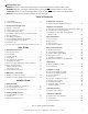
Safety Alert Key: • • • • DANGER! Indicates a hazardous situation which, if not avoided will result in death or serious injury. WARNING! Indicates a hazardous situation which, if not avoided could result in death or serious injury. CAUTION! Indicates a hazardous situation which, if not avoided, could result in minor or moderate injury. NOTICE: Used to address practices not related to personal injury. Table of Contents A. Congratulations . . . . . . . . . . . . . . . . . . . . . . . . . . . . . . . . .
B. Limited Lifetime Warranty Hearth & Home Technologies LIMITED WARRANTY Hearth & Home Technologies (“HHT”) and its respective brands extends the following warranty for HHT gas, wood, pellet and electric appliances purchased from an authorized HHT dealer and installed in the United States of America or Canada. Warranty starts with date of purchase by the original owner (End User) except as noted for replacement parts.
B. Limited Lifetime Warranty (continued) • This limited warranty does not extend to or include surface finish on the appliance or terminations, door gasketing, glass gasketing, glass discoloration, firebrick, pellet logs, kaowool or other ceramic insulating materials. Rust and/or corrosion on any of the metal surfaces, cast iron components, baffles, firepots, doors, or firebox area are not covered by this warranty.
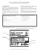
1 Listing and Code Approvals A. Appliance Certification MODEL: Twilight-II-B LABORATORY: Underwriters Laboratories, Inc. (UL) TYPE: Direct Vent Gas Appliance STANDARD: ANSI Z21.50-2003 • CSA2.22-M03 • UL307B This product is listed to ANSI standards for “Vented Gas Appliance Heaters” and applicable sections of “Gas Burning Heating Appliances for Manufactured Homes and Recreational Vehicles”, and “Gas Fired Appliances for Use at High Altitudes”. NOTICE: This installation must conform with local codes.
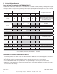
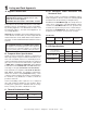
D. High Altitude Installations NOTICE: If the heating value of the gas has been reduced, these rules do not apply. Check with your local gas utility or authorities having jurisdiction. When installing above 2000 feet elevation: • In the USA: Reduce input rate 4% for each 1000 feet above 2000 feet. • In CANADA: Reduce input rate 10% for elevations between 2000 feet and 4500 feet. Above 4500 feet, consult local gas utility. Check with your local gas utility to determine proper orifice size. E.
Note: The following requirements reference various Massachusetts and national codes not contained in this document. H.
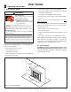
2 Operating Instructions User Guide • Keep remote controls out of reach of children. A. Gas Fireplace Safety • Never leave children alone near a hot fireplace, whether operating or cooling down. WARNING • Teach children to NEVER touch the fireplace. HOT SURFACES! Glass and other surfaces are hot during operation AND cool down. • Consider not using the fireplace when children will be present. Hot glass will cause burns.
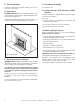
C. Fan Kit (optional) F. Fixed Glass Assembly If desired, a fan kit may be added. Contact your dealer to order the correct fan kit. See Section 11.G. D. Clear Space G. Remote Controls, Wall Controls and Wall Switches WARNING! DO NOT place combustible objects in front of the fireplace or block louvers. High temperatures may start a fire. See Figure 2.2.
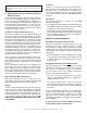
I. Lighting Instructions (IPI) The IPI system may be operated with two D-cell batteries. When using batteries, unplug the transformer. To prolong battery life, remove them when using the transformer. FOR YOUR SAFETY READ BEFORE LIGHTING WARNING: If you do not follow these instructions exactly, a fire or explosion may result causing property damage, personal injury or loss of life. A. This appliance is equipped with an intermittent pilot ignition (IPI) device which automatically lights the burner.
J. After Fireplace is Lit Initial Break-in Procedure • The fireplace should be run three to four hours continuously on high. • Turn the fireplace off and allow it to completely cool. • Remove fixed glass assembly. See Section 11.G. • Clean fixed glass assembly. See Section 3. • Replace the fixed glass assembly and run continuously on high an additional 12 hours. This cures the materials used to manufacture the fireplace. NOTICE! Open windows for air circulation during fireplace break-in.
3 Maintenance and Service Any safety screen or guard removed for servicing must be replaced prior to operating the fireplace. Doors, Surrounds, Fronts Frequency: Annually When properly maintained, your fireplace will give you many years of trouble-free service. We recommend annual service by a qualified service technician. By: Homeowner A. Maintenance Tasks-Homeowner • Inspect for scratches, dents or other damage and repair as necessary.
Exhaust Termination By: Qualified Service Technician Frequency: Seasonally Tools needed: Protective gloves, vacuum cleaner, dust cloths By: Homeowner Tools needed: Protective gloves and safety glasses. • Inspect exhaust termination for blockage or obstruction such plants, bird nests, leaves, snow, debris, etc. • Vacuum and wipe out dust, cobwebs, debris or pet hair. Use caution when cleaning these areas. Screw tips that have penetrated the sheet metal are sharp and should be avoided.
(Either cobrahead or SIT) Figure 3.2 Generic IPI Pilot Flame Pattern Heat & Glo LifeStyle Collection • Twilight-II-B • 2108-900 Rev.
4 Installer Guide Getting Started A. Design and Installation Considerations B. Tools and Supplies Needed Heat & Glo LifeStyle direct vent gas appliances are designed to operate with all combustion air siphoned from outside of the building and all exhaust gases expelled to the outside. No additional outside air source is required. Before beginning the installation be sure that the following tools and building supplies are available.
5 Framing and Clearances A. Selecting Appliance Location When selecting a location for the appliance it is important to consider the required clearances to walls (see Figure 5.1). NOTICE: Illustrations reflect typical installations and are FOR DESIGN PURPOSES ONLY. Illustrations/diagrams are not drawn to scale. Actual installation may vary due to individual design preference. WARNING! Risk of Fire or Burns! Provide adequate clearance around air openings and for service access.
B. Clearances OVERHANG NOTICE: Install appliance on hard metal or wood surfaces extending full width and depth. DO NOT install directly on carpeting, vinyl, tile or any combustible material other than wood. FINISHING MATERIALS A WARNING! Risk of Fire! Do not install appliance against vapor barriers or exposed insulation. Prevent contact with sagging or loose insulation. B A SIDING A • Locate and install appliance to all clearance specifications in manual.
C. Mantel and Wall Projections WARNING! Risk of Fire! Comply with all minimum clearances as specified. Framing or finishing material closer than the minimums listed must be constructed entirely of noncombustible materials (i.e., steel studs, concrete board, etc). TOP VIEW MEASURED FROM CORNER Combustible and Non-combustible Mantels- Indoor only CEILING NON-COMBUSTIBLE BOARD (SUPPLIED ON APPLIANCE) 1/2 IN. FIREPLACE HOOD INDOOR SIDE ONLY 12 11 10 35-3/4 9 8 13-5/8 12-5/8 7 6 Figure 5.
6 Termination Locations A. Appliance Opening Minimum Clearances = AREA WHERE APPLIANCE IS NOT PERMITTED G FP A D H E L X = AIR SUPPLY INLET FP = APPLIANCE OPENING M B P B FP F FP N B FP R FP I A A B* D E F G* H I * ** = 0 in ........................clearances above grade, veran(See Note 1) da, porch, deck or balcony = 12 in. .....................clearances to window or door that may be opened, or to permanently closed window. = 35-5/16 in. (non-vinyl) 64-5/16 in. (vinyl) ......
7 Appliance Preparation A. Removing Non-combustible Facing Material Assembly The non-combustible assembly is located on right-hand side of appliance (when looking from outdoor side of appliance). CAUTION APPLIANCE EXTERIOR Handle with care. • Non-combustible material may be damaged if dropped. • Hold non-combustible pieces in place. METAL HEARTH STRIP UNDER EDGE OF APPLIANCE • Remove and save two screws from upper bracket. • Remove non-combustible pieces. Figure 7.
Placing and Securing Appliance Place the appliance into position. Make sure flashing edges on the outdoor surround fit up tight to the framing. The diagram shows how to properly position, level, and secure the appliance (see Figure 7.2). Nailing tabs are provided to secure the appliance to the framing members. • Caulk behind flanges before securing to framing. APPLY HIGH TEMPERATURE SILICONE SEALANT TO CORNER EDGES FIREPLACE FLANGE • Place the appliance into position.
Apply housewrap or building paper For placement of combustible housewrap or building paper and non-combustible sheathing for the outside wall see Figures 7.5 and 7.6. Special care should be taken when choosing building materials for weather proofing (i.e. building wraps, sealant tapes, liquid sealants, rubberized flashings, etc.).
C. Installing Non-combustible Facing Material (Outdoor Side) • Attach the left and right side pieces to the framing members. (See Figure 7.9). NON-COMBUSTIBLE FACING MATERIAL WARNING Fire Risk. • Follow these instructions exactly. • Facing materials must be installed properly to prevent fire. • No materials may be substituted without authorization by Hearth & Home Technologies. • Center and attach two top boards (the two shorter pieces) to the framing members. See Figure 7.8. 49-5/8 in.
8 Gas Information A. Fuel Conversion C. Gas Connection • Make sure the appliance is compatible with available gas types. • Refer to Reference Section 13 for location of gas line access in appliance. • Conversions must be made by a qualified service technician using Hearth & Home Technologies specified and approved parts. • Gas line may be run through knockout(s) provided. B. Gas Pressure • Optimum appliance performance requires proper input pressures.
9 Electrical Information A. Wiring Requirements NOTICE: This appliance must be electrically wired and grounded in accordance with local codes or, in the absence of local codes, with National Electric Code ANSI/NFPA 70-latest edition or the Canadian Electric Code CSA C22.1. • Wire the appliance junction box to 110-120 VAC. This is required for proper operation of the appliance.
C. Intellifire Ignition System Wiring • Wire the appliance junction box to 110 VAC for proper operation of the appliance. WARNING! Risk of Shock or Explosion! DO NOT wire IPI controlled appliance junction box to a switched circuit. Incorrect wiring will override IPI safety lockout. • Refer to Figure 9.2, Intellifire Pilot Ignition (IPI) Wiring Diagram. • This appliance is equipped with an Intellifire control valve which operates on a 3 volt system.
D. Optional Accessories Optional fan and remote control kits require that 110-120 VAC be wired to the factory installed junction box before the appliance is permanently installed (see Figure 9.3). APPLIANCE INTERIOR SIDE Fan Installation To provide best airflow, we recommend positioning fan on the left side (as viewed from appliance interior side (see Figure 9.2). NOTE: It is recommended fan be installed prior to gas line installation.
E. Junction Box Installation If the box is being wired from the OUTSIDE of the appliance: HEAT SHIELD • Install the Romex™ connector (not included with appliance) in the side wrap. 14/2WG • Loosen two screws on the Romex connector, feed the necessary length of wire through the connector and tighten the screws. • Make all necessary wire connections.
10 Finishing A. Mantel and Wall Projections B. Facing Material WARNING! Risk of Fire! Comply with all minimum clearances as specified. Framing closer than the minimums listed must be constructed entirely of noncombustible materials (i.e., steel studs, concrete board, etc.) Failure to comply could cause fire. Inside Facing Material CEILING • May install combustible materials up to specified clearances on top, front and sides of appliance.
WARNING WARNING Risk of Fire • Non-combustible clearances must be maintained. • Sheetrock, wood or other combustibles must NOT be used as sheathing or facing in the noncombustible zone. • See Sections 3 & 8 for proper clearances. • See Section 1 for combustible/noncombustible definitions. Fire Risk. Finish all edges and fronts to clearances and specifications listed in manual. • Black metal columns may be covered with non-combustible material only.
NOTE: All finishing materials on top of exterior sheathing must be non-combustible for a minimum of 12 inches above and on both sides of the exterior face of the appliance. This non-combustible finishing material can be up to a maximum of 6 inches thick (6 inches maximum horizontal overhang) to allow for brick and stone alcoves (see Figure 8.5).
11 Appliance Setup A. Remove Fixed Glass Assembly See Section 11.G. B. Remove the Shipping Materials Remove shipping materials from inside or underneath the firebox. C. Clean the Appliance Clean/vacuum any sawdust that may have accumulated inside the firebox or underneath in the control cavity. E. Lava Rock and Ember Placement WARNING! Risk of Explosion! Follow ember placement instructions in manual. DO NOT place embers directly over burner ports. Replace ember material annually.
F. Install the Log Assembly Log Set Assembly: LOGS-MSR PILOT ASSEMBLY 2 3 4 5 1 6 CAUTION: Logs are fragile! Carefully remove the logs from the packaging. Remove the cardboard support from inside of fireplace. STEP 1. Before positioning the logs, refer to the installation manual for electric ember set-up and ember placement. GRATE TINE (HIDDEN) INDENT 1 GRATE BAR BOTTOM VIEW INDENT 1-inch BACK VIEW STEP 2.
2 3 1 STEP 4. LOG #3 (SRV2005-702): Position log #3 as shown by leaning it against log # 2 and resting the other end on the peak of the burner. DO NOT cover any port holes. 2 3 4 3/4 IN. 1 SHARP NOTCH STEP 5. LOG #4 (SRV2005-703): Locate the sharp notch on log #4 against the grate tine as shown. The smooth cutout on the bottom of log #4 should rest on the burner surface. The side of Log #4 must be 3/4 inch from the nearest port hole on the right side of log #4. DO NOT cover any port holes.
FLAT AREA Notch 4 2 3 5 2 1 1 STEP 7. LOG #6 (SRV2005-705): Locate the notch on log #6 and place it against the front right grate tine. Set the other end of the log so it rests on the flat area of log #1. The orientation of log #6 in relation to the grate tine is shown below. 3 2 4 6 1 5 Notch engaged with grate tine. Log Assembly Installed. 36 Heat & Glo LifeStyle Collection • Twilight-II-B • 2108-900 Rev.
G. Fixed Glass Assembly WARNING! Risk of Asphyxiation! Handle fixed glass assembly with care. Inspect the gasket to ensure it is undamaged and inspect the glass for cracks, chips or scratches. • DO NOT strike, slam or scratch glass. • DO NOT operate fireplace with glass removed, cracked, broken or scratched. • Replace as a complete assembly. Removing Fixed Glass Assembly • Remove wing nuts and glass clips around glass door. Remove glass door from the appliance.
12 Troubleshooting With proper installation, operation, and maintenance your gas appliance will provide years of trouble-free service. If you do experience a problem, this troubleshooting guide will assist a qualified service technician in the diagnosis of a problem and the corrective action to be taken. This troubleshooting guide can only be used by a qualified service technician. Contact your dealer to arrange a service call by a qualified service technician. A.
Intellifire Ignition System - (continued) Symptom 4. Pilot lights but continues to spark, and main burner will not ignite. (If the pilot continues to spark after the pilot flame has been lit, flame rectification has not occurred.) Possible Cause A. A shorted or loose connection in flame sensing rod. Corrective Action Verify all connections to wiring diagram in manual. Verify connections underneath pilot assembly are tight.
13 Reference Materials A. Appliance Dimension Diagram Dimensions are actual appliance dimensions. Use for reference only. For framing dimensions and clearances refer to Section 5.
B. Service Parts Twilight-II-B Service Parts Diagram Beginning Manufacturing Date: Jan. 2006 Ending Manufacturing Date: ______ 15 8 7 10 11 9 14 13 12 Wind Screen Assembly Log Set Assembly 2086-004MBK 2086-022 3 1 4 5 6 2 Part number list on following page. Heat & Glo LifeStyle Collection • Twilight-II-B • 2108-900 Rev.
Service Parts Twilight-II-B IMPORTANT: THIS IS DATED INFORMATION. When requesting service or replacement parts for your appliance please provide model number and serial number. All parts listed in this manual may be ordered from an authorized dealer.
Twilight-II-B Service Parts Beginning Manufacturing Date: Jan. 2006 Ending Manufacturing Date: ______ Valve Assembly Parts List 2 3 IPI Valve Assembly 4 1 5 7 6 8 9 10 11 12 13 14 16 15 IMPORTANT: THIS IS DATED INFORMATION. When requesting service or replacement parts for your appliance please provide model number and serial number. All parts listed in this manual may be ordered from an authorized dealer.
C. Contact Information Heat & Glo LifeStyle , a brand of Hearth & Home Technologies Inc. 7571 215th St, Lakeville, MN 55044 www.heatnglo.com Please contact your Heat & Glo LifeStyle dealer with any questions or concerns. For the location of your nearest Heat & Glo LifeStyle dealer, please visit www.heatnglo.com.