6826 STOP! Call Us First! DO NOT RETURN TO STORE. For immediate help with assembly or product information call our toll free number: 1-800-577-9663 or email: customerservice@backyardproductsllc.
(This page intentionally left blank.
ASSEMBLY MANUAL A Backyard Products Company 16826 08/26/2015 METROPOLITAN 12' x 7'-6" (365,8 x 228,6 cm) ACTUAL FLOOR SIZE IS 144" x 90" (365,8 x 228,6 cm) KEEP THIS MANUAL FOR FUTURE REFERENCE IMPORTANT! READ INSTRUCTIONS THOROUGHLY PRIOR TO BEGINNING ASSEMBLY. BEFORE YOU BEGIN • BUILDING RESTRICTIONS AND APPROVALS Be sure to check with local building department and homeowners association for specific restrictions and/ or requirements before building. .
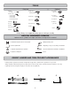
TOOLS Required ❑ Phillips Optional ❑ Tool Belt/ ❑ Utility Knife Screwdriver Nail Pouch ❑ Shingle Blades ❑ Drill / Driver ❑ 1/4" Drill Bit ❑ 3/8" Drill Bit ❑ 1/2" Drill Bit ❑ #2 Philips Drive Bit ❑ Tin Snips ❑ Caulk Gun (for drip edge) ❑ Chalk Line ❑ Paint Tools ❑ Hammer ❑ Nail Gun • gun nails ❑ Safety Glasses ❑ Level ❑ Pencil ❑ Ladder ❑ Tape Measure ❑ Square ❑ Gloves or Safety! Always use approved safety glasses during assembly.
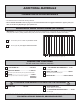
ADDITIONAL MATERIALS FOUNDATION OR FLOOR MATERIALS • This shed kit includes a complete wood floor system. • This shed kit does not include ANY leveling materials. • See the FLOOR LEVELING section on page 7 for recommended methods and suggested materials to properly level your floor, as this will vary depending on your specific site. REINFORCED WOOD FLOOR FRAME (OPTIONAL) IMPORTANT! The included floor has been designed for general use.
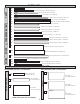
PARTS IDENTIFICATION AND SIZES Part identification letters are stamped on some parts. WOOD SIZE CONVERSION CHART Nominal Board Size Treated lumber is stamped: Actual Size 2" x 4"..............1-1/2" x 3-1/2" (3,8 x 8,9 cm) RS 1" x 4".................3/4" x 3-1/2" (1,9 x 8,9 cm) RS 2" x 3"..............1-1/2" x 2-1/2" (3,8 x 6,3 cm) Check these locations for part stamp. 1" x 3".................
CORNER/FREIZE TRIM TRIM PARTS LIST continued...
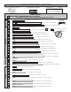
WALL PANEL & DOORS PARTS LIST x2 x3 3/8 x 23-7/8 x 96" (1 x 60,6 x 243,8 cm) x1 3/8 x 42 x 96" (1 x 106,7 x 243,8 cm) x1 3/8 x 48 x 72" (1 x 113,3 x 121,9 cm) x1 x1 3/8 x 42 x 96" (1 x 106,7 x 243,8 cm) x1 3/8 x 48 x 84-3/4" (1 x 122 x 215,3 cm) x1 3/8 x 48 x 96" 3/8 x 48 x 96" (1 x 121,9x 243,8 cm) (1 x 121,9x 243,8 cm) 3/8 x 48 x 84" (1 x 122 x 215,3 cm) x1 LEFT DOOR x1 RIGHT DOOR NAIL BOXES (not included) x2 BOXES x4 BOXES 3" (7,6 cm) 2" (5,1 cm) FASTENER/HARDWARE BAG x1
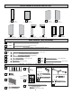
FLOOR LEVELING OPTIONS There are multiple ways to level your floor frame. Our recommended leveling method is shown below. Leveling materials are not included in this kit. PREFERRED METHOD - 4x4 TREATED RUNNERS • 3" Screws angled into 4x4. • (2) at each point frame • and 4x4 touch. O D 12" (30,5 cm) O R MATERIAL REQUIRED Measurements to center of 4x4's. x2 4" x 4" x 12' (10 x 10 x 365,8 cm)Treated Lumber 12" (30,5 cm) Fasteners for Frame to 4"x 4". (3" Screws shown as one option.
CONCRETE FOUNDATION Your kit contains all materials to construct a wooden floor. If you choose to install your kit on a concrete slab refer to the diagram below. Treated Sill Plate Caulk between sill plate and concrete.
FLOOR FRAME PARTS REQUIRED: x10 x2 x2 x44 2 x 4 x 87" (5,1 x 10,2 x 221 cm) 2 x 4 x 96" (5,1 x 10,2 x 243,8 cm) 3" (7,6 cm) Look for TREATED 2 x 4 x 48" (5,1 x 10,2 x 121,9 cm) Stamp BEGIN 1 Orient parts as shown on flat surface. Measure and mark. 2 Use two 3" nails at each mark. HINT: For easier nailing stand on frame. FINISH 3 You have finished your floor frame. Proceed to level and square frame.
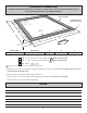
LEVEL AND SQUARE FLOOR FRAME Before attaching floor decking, it is important to level and square the floor frame. A level and square floor frame is required to correctly construct your shed. BEGIN See page 7 for the preferred floor leveling method. 1 2 Use level and check the frame is level before applying floor panels. 3 Check for frame squareness by measuring diagonally across corners. If the measurements are the same, the frame is square.
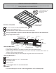
FLOOR PANELS PARTS REQUIRED: x50 2" (5,1 cm) 5/8 x 48 x 96" (1,6 x 121,9 x 243,8 cm) x1 Ensure your floor frame is square by installing one panel and squaring frame. BEGIN 1 Attach the 48 x 96" panel with the rough side up (painted-grid lines side) with the 48" edge and corner flush to the floor frame (Fig A). Secure panel with two 2" nails in the corners. 2 Move to the opposite side.
FLOOR PANELS PARTS REQUIRED: x1 x91 2" (5,1 cm) x1 5/8 x 42 x 96" (1,6 x 106,7 x 243,8 cm) 5 5/8 x 48 x 90" (1,6 x 60,6 x 122 cm) Continue installing panels with rough side up (painted grid lines). Use grid lines on panel for 2" nails 6" apart on edges, and 12" apart inside panels. 76 FINISH 7 You have finished attaching your floor panels.
IMPORTANT! Check the floor frame is level after installing floor panels. Re-level if needed. DOO R • The floor should be used as a stable work surface for wall construction. HINT: • Organize your assembly procedure during the build process to avoid over-handling of the walls.
BACK WALL FRAME PARTS REQUIRED: x2 SP x7 UX x2 TP x32 3" (7,6 cm) 2 x 4 x 48" (5,1 x 10,2 x 121,9 cm) 2 x 4 x 64" (5,1 x 10,2 x 162,5 cm) 2 x 4 x 96" (5,1 x 10,2 x 243,8 cm) BEGIN 1 Orient parts on edge on floor. Measure and mark. 2 Use two 3" nails at each mark and four 3" nails at seams 144" (365,8 cm) HINT: For easier nailing stand on frame.
BACK WALL PANELS PARTS REQUIRED: x45 GAA 48 x 72" (121,9 x 213,4 cm) x1 2" (5,1 cm) 3/4" GAUGE BLOCK • Ensure your wall frame is square by installing one panel and squaring frame. • Ensure top of panel is overhanging the top of frame by 4". 3 Place 48 x 72" panel onto wall frame with primed side up as shown. Use the gauge block to mark the 3/4" measurement on the wall stud. Secure panel with two 2" nails in the corners (Fig. A). 4 Move to the opposite end.
BACK WALL PANELS PARTS REQUIRED: x90 2" (5,1 cm) GAA x2 3/4" GAUGE BLOCK 48 x 72" (121,9 x 213,4 cm) 6 Place center 48" x 72" panel on frame as shown with primed side facing up. Nail using 2" nails 6" apart on edges and 12" apart inside panel. For squareness maintain 3/4" measurement along panel edges.
FRONT WALL FRAME PARTS REQUIRED: x1 x2 x1 x2 x4 x1 x1 RD SKA x34 2 x 4 x 16-1/2" (5,1 x 10,2 x 42 cm) 3" (7,6 cm) 2 x 4 x 40" (5,1 x 10,2 x 101,6 cm) FGA 2 x 4 x 57-5/8" (5,1 x 10,2 x 146,4 cm) UM 2 x 4 x 68" (5,1 x 10,2 x 172,7 cm) BLA 2 x 4 x 86" (5,1 x 10,2 x 218,4 cm) FHA 2 x 4 x 86-1/4" (5,1 x 10,2 x 219,1 cm) UN 2 x 4 x 94-1/2" (5,1 x 10,2 x 240 cm) BEGIN 1 For front wall, orient parts on edge on floor. Measure and mark. 2 Use two 3" nails at each mark and four 3" nails at seams.
FRONT WALL FRAME PARTS REQUIRED: x3 3 4 RD x12 3" (7,6 cm) 2 x 4 x 16-1/2" (5,1 x 10,2 x 41,9 cm) Orient parts on edge as shown. Measure and mark. HINT: For easier nailing stand on frame. Use two 3" nails at each mark. 115-3/8" (293,1 cm) 57-3/8" (145,7 cm) RD x3 27-1/2" (69,9 cm) 28-3/8" (72,1 cm) 27-1/2" (69,9 cm) 64" (162,6 cm) FINISH 5 You have finished building your front wall frame.
FRONT WALL PANELS PARTS REQUIRED: x1 3/8 x 48 x 96" (1 x 121,9 x 243,8 cm) x40 2" (5,1 cm) 3/4" GAUGE BLOCK Handle panels with care to avoid breakage. 1 Place 48 x 96" left panel primed side up onto wall frame centered in door opening as shown. • Ensure top of panel is overhanging the top of frame by 6". • Hold the 3/4" measurement along left edge of panel. Use a gauge block. 2 Nail panel with two 2" nails 6" (15,2 cm) apart. Maintain 64" (162,5 cm) measurement between studs and square frame.
FRONT WALL PANELS PARTS REQUIRED: x1 x1 3 3/8 x 48 x 96" (1 x 121,9 x 243,8 cm) x40 3/4" GAUGE BLOCK x2 2" (5,1 cm) 3" (7,6 cm) OO 2 x 3 x 69" (5,1 x 7,6 x 175,3 cm) TEMPORARY SUPPORT Place 48 x 96" right panel primed side up onto wall frame flush to left panel. • Hold the 3/4" measurement along right edge of panel. Use a gauge block. • Ensure top of panel is overhanging the top of frame by 6". 4 Nail panel with two 2" nails 6" (15,2 cm) apart.
FRONT WALL PANELS PARTS REQUIRED: x68 x2 3/8 x 23-7/8 x 96" (1 x 60,6 x 243,8 cm) 6 Place 23-7/8 x 96" panel onto wall frame flush to left 48 x 96" panel with primed side up as shown. • Ensure top of panel is overhanging the top of frame by 6". 7 Nail the panel using 2" nails 6" apart on edges. 8 Repeat steps 6 and 7 to attach the right panel.
BACK WALL INSTALLATION PARTS REQUIRED: x2 JDA x2 TEMPORARY 3" (7,6 cm) x12 2 x 4 x 80-11/16" (5,1 x 10,2 x 204,9 cm) 3" (7,6 cm) x25 2" (5,1 cm) BEGIN Stand backwall on floor. It is important to secure the backwall in the following order. ENSURE 4" MEASUREMENT IS AT TOP OF BACK WALL ASSEMBLY. 1 Center back wall assembly on the 144" floor dimension. 2 Use (2) JDA as a temporary brace. Level wall and secure JDA with two 3" screws (Fig. A). 4" (10,2 cm) Fig.
FRONT WALL INSTALLATION PARTS REQUIRED (TEMPORARY): x2 x4 BOA 3" (7,6 cm) x8 2 x 4 x 93-3/16" (5,1 x 10,2 x 236,7 cm) 3" (7,6 cm) x14 2" (5,1 cm) BEGIN Stand front wall on floor. 1 Center front wall assembly on the 144" front floor dimension. 2 Use (2) BOA as temporary braces. Level wall and secure BOA with two 3" screws. (3 14 6 5 4" ,8 cm ) Fig. A BOA x2 3 First, nail lower edge of panel to floor frame using 2" nails 6" apart. Angle nail to hit floor frame (Fig. B).
DOUBLER INSTALLATION PARTS REQUIRED: x1 x1 x1 x1 SP 2 x 4 x 48" (5,1 x 10,2 x 122 cm) FGA x32 3" (7,6 cm) 2 x 4 x 57-5/8" (5,1 x 10,2 x 146,4 cm) 2 x 4 x 96" (5,1 x 10,2 x 243,8 cm) TP FHA 2 x 4 x 86-1/4" (5,1 x 10,2 x 219,1 cm) BEGIN 1 For back wall, orient parts on flat on top of wall frame. BE SURE DOUBLERS ARE FLUSH. 2 SP Use two 3" nails at each stud and four 3" nails at seam. Flush 3" (7,6 cm) Nails Flush TP Flush Stagger seams 3 For front wall, use 3" nails as shown.
OUTER RAFTER INSTALLATION PARTS REQUIRED: x2 x8 BOA 3" (7,6 cm) 2 x 4 x 93-3/16" (5,1 x 10,2 x 236,7 cm) BEGIN 1 2 3 4 Rest one outer rafter on front and back wall doublers. Ensure rafter is flush to back wall panel (Fig. A) and flush to end of back wall doubler (Fig. B). Secure back of outer rafter using 3" screw installed centered into outer rafter end (Fig. A) and afterwards toenailed into inside of rafter (Fig. B). DO NOT OVER-DRIVE SCREW THROUGH PANEL.
OUTER RAFTER INSTALLATION PARTS REQUIRED: 6 x2 x20 H 2.5 Tie Plate Attach tie plates with 2" nails as shown. 2" (5,1 cm) Nails FINISH 7 You have finished installing your outer rafters.
RAFTERS PARTS REQUIRED: x9 x54 BOA 3" (7,6 cm) 2 x 4 x 93-3/16" (5,1 x 10,2 x 236,7 cm) BEGIN 1 Starting at end as shown, measure and mark location of each rafter. 2 Place rafter on front and back wall doublers. Line up rafter centered with marks. Ensure rafter is flush to back wall panel (Fig. A) and flush down on top of back wall doubler (Fig. B). 3 Secure back of rafter using 3" screw installed centered into outer rafter end (Fig. A). DO NOT OVER-DRIVE SCREW THROUGH PANEL.
OUTER RAFTER INSTALLATION PARTS REQUIRED: 7 x9 x90 H 2.5 Tie Plate 1-1/2" (3,8 cm) Attach (9) tie plates with 1-1/2" nails as shown. • Attach far left tie plate reversed position from others (Fig. A). 1-1/2" (3,8 cm) Nails • HINT: Look for the"Simpson" name on the tie plate. Fig. A RIGHT R DOO LEFT FINISH 8 You have finished installing your rafters.
SIDE WALL PANELS PARTS REQUIRED: x1 x1 OO x2 3" (7,6 cm) TEMPORARY SUPPORT 1-1/2 x 2-1/2 x 69" (3,8 x 6,3 x 175,3 cm) 3/8 x 42 x 96" (1 x 106,7 x 243,8 cm) x1 x3 3/8 x 42 x 96" (1 x 106,7 x 243,8 cm) x1 x1 3/8 x 48 x 84-3/4" (1 x 121,9 x 215,3 cm) 2" (5,1 cm) x12 1-1/2" (3,8 cm) 3/8 x 48 x 84-3/4" (1 x 121,9 x 215,3 cm) BEGIN 1 Attach OO as a support-ledge to to help install side wall panels. Measure down from floor 1" and mark. Ensure OO is level and centered.
SIDE WALL PANELS (continued) PARTS REQUIRED: x45 4 x16 1-1/2" (3,8 cm) 2" (5,1 cm) Place 48 x 84-3/4" panel onto side wall flush with bottom of 42 x 96" panel with primed side up, as shown. Secure panel with 2" nails in three corners (Fig. E). Ensure the measurement between the panel edges are the same along the entire length (Fig. B). Angle nails to hit floor frame (Fig. C). Primed side up Fig. E Same Measurement 1-1/2" Nails Fig. C Flush Fig.
SIDE WALL STUDS PARTS REQUIRED: x2 x2 x2 x18 JCA 2 x 4 x 72-5/8" (5,1 x 10,2 x 184,5 cm) x1 JDA 2 x 4 x 80-11/16" (5,1 x 10,2 x 204,9 cm) 3" (7,6 cm) TEMPORARY GUIDE RD 2 x 4 x 16-1/2" (5,1 x 10,2 x 41,9 cm) JEA 2 x 4 x 86-1/8" (5,1 x 10,2 x 218,8 cm) BEGIN 1 Install JDA centered at seam of side wall panels (Fig A). Use a square to ensure 90 degree squareness of studs (JDA, JCA and JEA). Flush to rafter Center JDA on seam of wall panels. Flush to rafter Flush to rafter Fig.
SIDE WALL PANELS PARTS REQUIRED: x58 9 Measure, align and mark side wall studs 24" from center of panel seam as shown. 9 Nail side wall panels to inside wall studs using 1-1/2" nails 6" apart along panel seam and 12" apart in middle of panels as shown. 20" (50,8 cm) 20" (50,8 cm) 1-1/2" (3,2 cm) Nails 6" (15,2 cm) 12" (30,5 cm) 10 Repeat Step 9 to nail the opposite side panels. FINISH 11 You have finished nailing your SIDE WALL PANELS.
STOP CHOOSE YOUR SIDE WALL WINDOWS LOCATION AT THIS TIME. WINDOWS ON LEFT SIDE WALL WINDOWS ON RIGHT SIDE WALL SIDE WALL WINDOW FRAMING PARTS REQUIRED: x4 x16 RD 3" (7,6 cm) 2 x 4 x 16-1/2" (5,1 x 10,2 x 41,9 cm) BEGIN 1 Choose the side wall you want to install your windows on. 2 From inside, measure and mark locations of (4) RD. Secure with 3" screws.
SIDE WALL WINDOW CUTOUT PARTS REQUIRED: 3/8" (1,0 cm) Drill Bit 3 Using a 3/8" drill bit, drill a hole through both wall panels in each corner of window framing. Pre-drill hole 3/8" (1.0 cm) 3 From outside, mark straight lines connecting the holes. 4 Cut along lines using a saw. Carefully trim panel openings after cutting as necessary. FINISH 5 You have finished preparing your SIDE WALL for window installation.
ROOF PANELS PARTS REQUIRED: x1 7/16 x 11-7/8 x 60-1/4" (1,1 x 30,2 x 152,7 cm) x1 x4 2" (5,1 cm) 7/16 x 11-7/8 x 96" (1,1 x 30,2 x 244 cm) Roof panels may cause serious injury until securely fastened. BEGIN 1 Place the 11-7/8 x 96" lower roof panel with the rough side up (painted-grid lines side) with 2-7/8" overhang from back wall panel (Fig A). Ensure the panel measures 3/4" (1,9 cm) along the length of the rafter (Fig. B). Secure panel with 2" nails as shown.
ROOF PANELS PARTS REQUIRED: x4 2" (5,1 cm) GAA x1 3/4" GAUGE BLOCK 7/16 x 48 x 96" (1,1 x 121,9 x 244 cm) Roof panels may cause serious injury until securely fastened. 3 You must square the roof by attaching one 48 x 96" panel at this time. You will use the panel's long edge as a lever to bring your roof into square. 48 x 96" (121,9 x 244 cm) Place the 48 x 96" roof panel as shown with the rough side up.
ROOF PANELS PARTS REQUIRED: x1 5 7/16 x 11-7/8 x 96" (1,1 x 30,2 x 244 cm) x167 x2 2" (5,1 cm) 7/16 x 48 x 96" (1,1 x 121,9 x 244 cm) Nail the first 48 x 96" roof panel using 2" nails 6" apart on edge and 12" apart inside panel. Flush Fig. F Locate the second 48 x 96" roof panel with the rough side up flush to first panel along edge and at both corners (Fig. E, F). Repeat nailing pattern. R O ) ) cm O D 6" 5,2 (1 " cm 12 0,5 (3 ) ) " cm 12 0,5 (3 6" 5,2 (1 cm Flush Fig.
RAFTER EXTENSIONS PARTS REQUIRED: x11 x28 2" (5,1 cm) BRA 2 x 3 x 10-1/2" (5,1 x 7,6 x 26,7 cm) BEGIN 1 Line up each rafter extension BRA 90 degrees square with rafters as shown. Secure rafter extensions with screws through roof panels (Fig. A). • Use screws at rafter ends as a guide to line up BRA with rafter ends. • At roof panel seams use 4 screws (Fig. B). • DO NOT OVER-DRIVE SCREWS THROUGH ROOF PANELS. • Ensure BRA extensions at each side are flush with side wall panels (Fig. C). Fig. B Fig.
SIDE RAKE FRAMING PARTS REQUIRED: x2 x2 x16 BPA 2" (5,1 cm) 1 x 3 x 33 - 1/8" (2,5 x 7,6 x 84,1 cm) HJ 1 x 3 x 72" (2,5 x 7,6 x 182,8 cm) BEGIN 1 Align BPA edge flush with rafter extension BRA (Fig A). Attach with (3) 2" nails (Fig B). 2 Attach HJ flush with BPA with (5) 2" nails. (Fig A, FIg. B) 3 Repeat Steps 1-2 on opposite side. Flush Fig. B 2" Finish Nail Angled Ends Flush Flush at seam Fig. A BRA BPA HJ FINISH 4 You have finished installing your gable rake framing.
SIDE SOFFIT PARTS REQUIRED: x20 2" (5,1 cm) x2 3/8 x 5-1/4 x 95-1/2" (1 x 13,3 x 242,5 cm) BEGIN 1 Attach 95-1/2" soffit BR primed side down flush to front wall panel (Fig. A). Secure to side rake frame BPA using (7) 2" finish nails (Fig. A, B). BPA BPA Fig. A Flush BR FRONT WALL PANEL Flush 95-1/2" (242,5 cm) 2" Finish Nails Fig. B BPA Flush BR 2" Finish Nails 2 Repeat Step 1 on opposite side. FINISH 3 You have finished installing your side soffit panels.
FRONT SOFFIT PARTS REQUIRED: x24 x1 2" (5,1 cm) x1 3/8 x 10-3/8 x 75-1/2" (1 x 26,3 x 191,8 cm) 3/8 x 10-3/8 x 79-5/8" (1 x 26,3 x 202,2 cm) BEGIN Attach 75-1/2" soffit primed side down under rafter extensions BRA flush to side wall soffit (Fig. A). Ensure soffit is flush to front wall panel. Secure to BRA using (12) 2" finish nails as shown. Toenail at right side of soffit into BRA (Fig. B). 1 75-1/2" (191,8 cm) BRA 2" Finish Nails Flush Fig. A BRA Fig.
FRONT FASCIA TRIM PARTS REQUIRED: x1 x24 HHA 2" (5,1 cm) 19/32 x 3-1/2 x 60-3/8" (1,5 x 8,8 x 153,4 cm) x1 ZX 19/32 x 3-1/2 x 96" (1,5 x 8,8 x 243,8 cm) BEGIN Measure 1/4" past left roof panel and line up HHA primed side out and flush up under roof panels (Fig. A). Right side of HHA is approximately 3/4" from center of rafter extension BRA. Secure HHA with 2" finish nails into BRA (Fig. B). 1 BRA 60-3/8" (153,4 cm) 1/4" 3/4" APPROXIMATELY Flush Flush 2" Finish Nails 1/4" HHA Fig.
SIDE FASCIA TRIM ASSEMBLY PARTS REQUIRED: x1 x1 x2 BXR x2 BXL x2 19/32 x 3 - 1/2 x 59 - 1/4" (1,5 x 8,8 x 150,4 cm) 19/32 x 3 - 1/2 x 59 - 1/4" (1,5 x 8,8 x 150,4 cm) x28 BQA 2" (5,1 cm) 2 x 3 x 33-1/8" (5,1 x 7,6 x 84,1 cm) ZT 19/32 x 3-1/2 x 48" (1,5 x 8,8 x 121,9 cm) OY 2 x 3 x 72" (5,1 x 7,6 x 182,8 cm) BEGIN To build left side fascia assembly place BQA and OY end to end on a flat surface (Fig. A). 1 Fig. A BQA OY Place BXR and ZT primed side up and flush with BQA and OY.
SIDE FASCIA TRIM PARTS REQUIRED: x18 x12 x1 2" (5,1 cm) 2" (5,1 cm) LEFT FASCIA ASSEMBLY RIGHT FASCIA ASSEMBLY x1 BEGIN 1 Place left side fascia assembly between roof sheathing and side soffit (Fig. A). 2 Hold left side fascia assembly tight to front fascia trim (Fig. B). 3 Secure fascia assembly under roof panels flush with front fascia board using (7) 2" screws through roof sheathing (Fig. A).
REAR FASCIA TRIM PARTS REQUIRED: x1 x2 HBA x10 19/32 x 3-1/2 x 59-1/2" (1,5 x 8,8 x 151,1 cm) x1 ZX 3" (7,6 cm) 2" (5,1 cm) x16 19/32 x 3-1/2 x 96" (1,5 x 8,8 x 243,8 cm) x1 GKA 2" (5,1 cm) 2 x 3 x 59-1/2" (5,1 x 7,6 x 151,1 cm) x1 PT 2 x 3 x 96" (5,1 x 7,6 x 243,8 cm) BEGIN 1 Place PT and GKA flush to roof sheathing and flush to back wall panel (Fig. A). 2 Secure PT and GKA with 2" wood screws through roof sheathing (Fig. A). 2" Screw Fig.
BACK CORNER TRIM PARTS REQUIRED: x2 x1 x1 x24 2" (5,1 cm) 3/8 x 2 x 68-3/4" (0,9 x 5,1 x 174,6 cm) 3/8 x 2 x 69-1/4" (0,9 x 5,1 x 175,8 cm) 3/8 x 2 x 69-1/4" (0,9 x 5,1 x 175,8 cm) ¸1 BEGIN 2 Place 68-3/4" back corner trim flush to bottom of back soffit board (Fig. A, B, F) and flush with side panel along the length (Fig. A). Attach using (6) 2" finish nails into corner wall framing (Fig. A, C). Space nails equally (Fig. C). Place 69-1/4" back side corner trim angled end up (Fig.
SIDE CORNER TRIM PARTS REQUIRED: x1 x1 x12 3/8 x 2 x 93-1/4" (0,9 x 5,1 x 236,8 cm) 3/8 x 2 x 93-1/4" (0,9 x 5,1 x 236,8 cm) ¸1 BEGIN Attach 93-1/4" side corner trims on both sides flush with front wall panel. Use (6) 2" finish nails to secure side trim to side wall (Fig. A, B, C). Fig. B 2" Finish Nail Flush Fig. A Fig. C Flush FINISH 2 FRONT WALL PANEL You have finished attaching your side corner trim boards.
FRONT FRIEZE TRIM PARTS REQUIRED: x1 x12 2" (5,1 cm) 3/8 x 2 x 72" (0,9 x 5,1 x 182,9 cm) x1 3/8 x 2 x 73-3/8" (0,9 x 5,1 x 186,4 cm) ¸1 BEGIN Attach 72" and 73-3/8" front horizontal frieze boards using 2" finish nails evenly spaced as shown (Fig. A). Note: The frieze boards will be flush with the side trim (Fig. B). Fig. B Fig. A 72" 73-3/8" Flush 2" Finish Nail Flush Flush Flush FINISH 2 You have finished attaching your front frieze trim.
FRONT CORNER TRIM PARTS REQUIRED: x2 x12 2" (5,1 cm) 3/8 x 2 x 91-1/4" (0,9 x 5,1 x 231,7 cm) ¸1 BEGIN Attach both vertical 91-1/4" front corner trim on both sides, flush to edge of installed side trim using (6) 2" finish nails evenly spaced in each trim board (Fig. A, B, C). Fig. B Fig. A Flush 2" Finish Nail Fig. C Flush 91-1/4" (231,7 cm) FINISH 2 You have finished attaching your front corner trim boards.
DOORS PARTS REQUIRED: x4 x1 3" (7,6 cm) OO x2 1-1/2 x 2-1/2 x 69" (3,8 x 6,3 x 175,3 cm) 1-1/4" (3,2 cm) HINT: Look for 3/8" SPACER attached to doors. x1 x1 Left Door x1 GAA Right Door 1 x 3 x 5" (2,5 x 7,6 x 12,7 cm) BEGIN 1 Orient parts as shown on flat surface. (right) and green (left) on hinge board. 2 Attach temporary support OO with 3" screws in middle and at ends as shown. Tighten securely. 3 Attach temporary support GAA with two 1-1/4" screws as shown. Tighten securely.
DOORS PARTS REQUIRED: x1 4 x13 3" (7,6 cm) OO 1-1/2 x 2-1/2 x 69" (3,8 x 6,3 x 175,3 cm) Attach temporary support OO as a ledger board flush under wall panels for doors to rest on using 3" screws (Fig. A). OO Flush against wall panels Fig. A OO 5 Center doors on panel seam as shown (Fig. B). Check ledger board is still flush under panels. 6 Screw hinge boards into wall frame and floor using ten 3" screws as shown. Make sure screws go into framing and floor (Fig. C, D).
DOOR TRIM PARTS REQUIRED: x2 x2 x1 AH 64" Metal Threshold 3/4" (1,9 cm) x11 19/32 x 2-1/2 x 26-5/8" (1,5 x 6,3 x 67,6 cm) Bagged separately / special coating FDA x5 2" (5,1 cm) x54 3/4" (1,9 cm) 19/32 x 2-1/2 x 55-7/8" (1,5 x 6,3 x 141,9 cm) BEGIN 1 Secure hinge boards from inside using 3/4" screws as shown (Fig. A). 2 Position FDA centered and square with bottom door trim as shown. Secure with five 3/4" screws from inside of doors (Fig. B).
DOOR WEATHERSTRIP PARTS REQUIRED: x2 x10 2" (5,1 cm) OO 1-1/2 x 2-1/2 x 69" (3,8 x 6,3 x 175,3 cm) BEGIN 1 Center OO vertically on the left door in the door opening flush with the edge of door (Fig. A). 2 Secure using (5) 2" screws through outside trim into OO (Fig. B) 3 Repeat Steps 1-2 to install OO on right door. FINISH 4 You have finished installing your door stiffeners. Fig. B Center OO in door opening. IT IS IMPORTANT TO HOLD THESE DIMENSIONS 7/8" (2,2 cm) 5/8" (1,6 cm) OFFSET Fig.
DOOR HARDWARE PARTS REQUIRED: 1/2" (13 mm) Drill Bit 1/4" (6 mm) Drill Bit BEGIN 1 Measure and mark location of hole on outside of right door as shown (Fig. A). Pre-drill hole with 1/4" drill. 2 Re-drill hole with 1/2" drill (Fig. B). Keep drilled hole square to trim to avoid breaking edge of 1-1/2" x 2-1/2" door stiffener. Flush RIGHT DOOR. Fig. B Fig.
DOOR HARDWARE PARTS REQUIRED: Handle (locking) with Screws 3-Point Door Locking Mechanism 1-1/4” x2 1-1/4” x2 3/4” Tech Screw with drill point 1-1/4” x8 1/2" (13 mm) Drill Bit 1/4" (6 mm) Drill Bit x4 x1 x1 Secure backplate with 1" screws and handle with 1-1/4" screws as shown. Set Screw RIGHT DOOR Backplate T GH RI R O DO 1/2” DRILL THROUGH 1-1/4" Wood Screw 1-1/4" Pan Head Screw Pre drill for screws.
DOOR HARDWARE See following pages for mounting locations of brackets and plates. Plate Washer 1-1/4" Pan Head Screw UPPER BRACKET (with offset) Orient bracket as shown. 3/4" Tech Screw Washer 3/4" Tech Screw Washer LOWER BRACKET (without offset) Orient bracket as shown.
DOOR HARDWARE TOP of Door 2-1/4" Weatherstrip RIGHT DOOR LEFT DOOR 45o Make sure rods are straight up and down when locating brackets.
DOOR HARDWARE FRAMING Drill with 3/8" bit to 2" depth. PLATE Align Plates with vertical rod points. Drill-thru with 3/8" drill bit to 2" depth into header and floor.
FRONT WINDOWS PARTS REQUIRED: x6 9" x 27" (22,8 x 68,5 cm) x3 ¸1 3/4" (1,9 cm) BEGIN 2 Apply high quality exterior-grade caulk behind frame near edge before installing to seal window. From outside of shed, position window in center of opening and level. Use two screws at top of windows. Maintain equal distance on both sides of door. Do not fully tighten screws. 2 Screws per window 2 Screws per window EQUAL HINT: Caulk behind frame near edge before installing.
FRONT WINDOWS PARTS REQUIRED: x2 BSA 19/32 x 2-1/2 x 91" (1,5 x 6,3 x 231,1 cm) 3 x19 2" (5,1 cm) x4 EY 19/32 x 2-1/2 x 9" (1,5 x 6,4 x 22,9 cm) Center BSA over door. Secure using (7) 2" finish nails as shown. Do not nail into window flange. Flush Mark Center BSA 3/4" (1,9 cm) Centered Flush 4 Position EY at ends and in between window frame as shown. Secure using (8) 2" finish nails. Remove 1-1/4" screws.
FRONT WINDOWS PARTS REQUIRED: x12 3/4" (1,9 cm) 6 Install (12) 3/4" screws from inside, as shown. Do not screw into window flange. Install 3/4" (1,9 cm) screws from inside. FRAMING BEYOND INSIDE OF SHED Install 3/4" (1,9 cm) screws from inside. FINISH 7 You have finished installing your window.
SIDE WINDOWS PARTS REQUIRED: x8 Window 16-1/4" x 22-1/4" (41,3 x 56,5 cm) x1 x4 JFA 2" (5,1 cm) 2" (5,1 cm) 19/32 x 2-1/2 x 41-1/4" (1,5 x 6,3 x 104,8 cm) x2 BEGIN Mark center of window frames as shown. 2 CENTER CENTER Seal windows with high-quality exteriorgrade caulk before installing. Caulk behind frame near edge. 3 Attach windows using (8) 2" screws as shown. Ensure windows are level. 2" Screws 4 Measure up from bottom of panel 42-1/2" (Fig.A). Center JFA with panel seam.
SIDE WINDOWS PARTS REQUIRED: x13 x2 CY 19/32 x 2-1/2 x 24-1/2" (1,5 x 6,3 x 62,2 cm) x2 ZZ 19/32 x 3-1/2 x 24-3/8" (1,5 x 8,8 x 61,9 cm) x1 JFA 5 2" (5,1 cm) 19/32 x 2-1/2 x 41-1/4" (1,5 x 6,3 x 104,8 cm) Center CY flush with JFA. Secure with (3) 2" finish nails. CY 2" Finish Nails Flush Flush JFA 6 Center ZZ between windows and flush with JFA. Secure with (3) 2" finish nails. ZZ 2" Finish Nails CENTER CENTER JFA Flush 7 Position JFA flush with CY. Secure with (4) 2" finish nails.
VENTS PARTS REQUIRED: x2 ¸1 x12 1/2" (1,3 cm) 8 x 16" (20,3 x 35,6 cm) BEGIN Locate and mark for two vents in side walls as shown. (1) at top and (1) at bottom Cut out marked openings. Caulk behind vent flanges. 2 Secure using 1/2" (1,3 cm) screws. FINISH 3 You have finished installing your vents.
PAINT & CAULK - NOT INCLUDED - • Use acrylic latex caulk that is paintable. Caulk at all horizontal and vertical seams, between the trim and walls, and all around the door trim. • Use a high quality exterior acrylic latex paint. When painting your building, there are a few key areas that can be easily overlooked that must be painted: • Bottom edge of all siding and trim • Inside of doors and all 4 edges Note: Prime all un-primed exterior wood before painting.
SHINGLES - NOT INCLUDED • Follow directions provided by manufacturer and these instructions. Familiarize yourself with a 3-Tab Shingle. Notch SHINGLE NAIL PATTERN 1/2" (1,3 cm) 1" (2,5 cm) Sealing Strip Notch 1" (2,5 cm) Half A Rain Slot Full Rain Slot NAILS NEVER DRIVE FASTENERS INTO OR ABOVE SEALING STRIPS. ¸1 BEGIN Install first starter row upside down, color up and flush to drip edge at bottom of roof panel. Use (4) nails per shingle.
SHINGLES continued... 3 Install second row of shingles flush at top of first row's rain slots. Ensure flush to drip edge at front side, stagger each row. DOOR Notch BACK OF SHED Flush with rain slots. 4 Continue installing rows of shingles by staggering at front. Flush with rain slots. 1" (2,5 cm) Notch BACK OF SHED 5 Continue installing rows of shingles to the front of the shed. At the front edge of the shed make sure there is a maximum of 5" or less to the rain slot, as shown below.
SHINGLES - DRIP EDGE 7 Install drip edge over top shingle row with 1" overhang over roof edge. 1" (2,5 cm) 8 Using your shingle hooked blade carefully cut shingles on a flat surface along the rain slots, using a chalk line for reference. 9 Align remaining shingles with edge of the front drip edge. FINISH 10 You have finished shingling your roof.
WARRANTY REGISTRATION Please complete your warranty registration to properly validate your warranty. Register your product online at: www.OnlineWarranty.net LIMITED CONDITIONAL WARRANTY* Backyard Storage Solutions, LLC warrants the following: 1. Every product is warranted from defects in workmanship and manufacturing for 1 year. 2. All accessories, hardware and metal components are warranted for 2 years. 3. All Oriented Strand Board (OSB) is warranted for 2 years 4.