HEARTLAND ® 1260 E. VanDeinse St.
If the information in this manual is not followed exactly, a fire or explosion may result causing property damage, personal injury, or death. —FOR YOUR SAFETY— DO NOT STORE OR USE GASOLINE OR OTHER FLAMMABLE VAPOURS OR LIQUIDS IN THE VICINITY OF THIS APPLIANCE. • Do not use the range as a heater. • Do not heat unopened glass or metal containers in the oven. • Grease accumulation is the cause of many cooking fires. Clean the oven and broiler compartment regularly.
HEARTLAND Heart Heartl Heartl land andd an ® Electric Self Clean Models 6210/8210 CONSUMER WARRANTY ENTIRE PRODUCT – LIMITED ONE YEAR WARRANTY AGA MARVEL warrants the replacement or repair of all parts, of this appliance which prove to be defective in material or workmanship, with the exception of the painted or porcelain enamel finish or plated surfaces, for one year from the date of original purchase.
TABLE OF CONTENTS Description ........................................ Page Description ....................................... .Page 1. Warranty ..................................................................3 29. Minute Minder.......................................................31 2. Assembly and Installation ....................................... 5 30. Time Bake .......................................................... 29 3. Cresting Panel Assembly..........................................
Assembly and Installation To fully enjoy your new range, it is important that you read this booklet thoroughly. Note: Please check for any damage that may have occurred during shipping. In the unlikely event that you find any shipping damage, inform your dealer immediately! Caution when unpacking: Lift the range by the bottom skirt, do not lift by nickel trim. Unpacking: Note: to avoid injury, please wear safety equipement, glasses and gloves, while you are unpacking your new range.
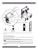
Sheet metal screw Steel washer VE O ST OP T Machine screw Bracket Gasket - Peel off backing and stick on. Steel Washer Sheet metaI screw (black) Machine screw Gasket -Remember when working with the cabinet, the cabinet is top heavy. Use your hand to support it during installation. -Place box on the floor close to stove. -With a helper,lift closet assembly from box.
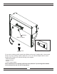
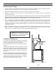
Deflector Back of cabinet Sheet metal screw 3 1/2" x 10" Exhaust adaptor If you are not venting outside, attach the deflector to the rear of cabinet with 4, sheet metal screws. If you are venting outside, attach the 3 1/2" x 10" exhaust adaptor with 4, sheet metal screws. Fasten your exhaust ducting to the adaptor. Small boxcontains: - hardware package - deflector - 3 1/2"x10 exhaust adapter Note: maximum run of ducting is 25 linear feet (subtract 5' per 90 deg elbow added to the exhaust line and 2.
CONNECTING POWER TO THE CABINET After your exhaust hood has been installed the very last thing to do is to connect the multipin plug to the range. The receptacle is located at the rear of the stove under the metal cover. Remove the screw securing the cover to the back of the range and remove the cover. Remove the cable clamp from the stove which is located just above the cover.
Positioning the Range 1. When the range is fully assembled, recheck all electrical connections especially between the exhaust hood and the back of the range. As well, check that all nuts and bolts have been tightened. 2. Ensure teflon gliders and flooring are clean, (as described on page 5 under "Gliders"). 3. Caution: On flooring with very rough surfaces or deep, large grooves the appliance may have to be lifted and slowly slid into position. 4.
Exhaust Hood Your range is equipped with a variable speed range hood that may be either vented directly to the outside, or may be installed ventless. An exhaust filter is included with your hood. The filters should be cleaned periodically in soapy water. Extras are available from your dealer or directly from Heartland. Please order 4 or more filters at one time to save freight and handling charges. Ventless Installation Your unit is already set up for ventless operation.
Vented Installation, Tools, Material, and Dimensions Tools required to install vented hood: - Hammer - Slot screwdriver - Pliers - Electric drill - Measuring tape - 3/32” (3 mm) Drill bit - 1/2” (13 mm) Drill bit - Sabre saw OR Keyhole saw Materials Required: - 3 1/4" x 10" (82.55 mm x 254 mm) metal duct—enough to go through wall or attic to outside. Elbows as required. - Roof cap or wall venthood - Caulking to seal around duct - #6 x 1/2” (82.
Important Safety Instructions 1. PROPER INSTALLATION- BE SURE YOUR APPLIANCE IS PROPERLY INSTALLED AND GROUNDED BY A QUALIFIED TECHNICIAN. Have the installer show you the location of the circuit breaker or fuse. Mark it for future reference. 2. Never use your appliance for warming or heating the room. Use only for its intended use as described in this manual. 3. Do not leave children alone. Children should not be left alone or unattended in area where appliance is in use.
- Always turn the surface units off before removing cookware. - When preparing flaming foods under the hood, turn the fan on. - Use care when touching the cooktop. The smooth surface of the cooktop will retain heat and may be hot enough to burn even though it may appear dark in color after the controls have been turned off. - Use little fat for effective shallow or deep fat frying. Filling the pan too full of fat can cause spillovers when food is added.
Oven Safety Do not touch heating elements or interior surfaces of oven—heating elements may be hot even though they are dark in colour. Interior surfaces of an oven become hot enough to cause burns. During and after use, do not touch, or let clothing or other of oven until they have had time to cool.
FEATURES - USING THE SURFACE ELEMENTS Cooking Controls (Surface Units) 30" Model 48" Model G G A C A B C B E D F A - 1200 watt radiant 5 1/2" dia. A - 1200 watt radiant 5 1/2" dia. B - 2000 watt radiant 7 1/2" dia. B - 2000 watt radiant 7 1/2" dia. C - 2500 watt dual radiant 9" dia.- 1000 watt C - 2500 watt dual radiant 9" dia.
How to Set Smooth Cooktop Burners Burners A,B, E & F: - Push the knobs in and turn in either direction to the setting desired. - The higher number selected represents the higher temperature . - At both the low (1) and high(7) settings, the control will "click" into position. Control will also "click" and pop back up, in the off (0) position. - Please be sure control knob is turned off (0) when your finished cooking.
About the smooth cooktop surface units… The cooktop features heating units beneath a smooth Eurokera Ceramic surface. Note: A slight odor is normal when a new cooktop is used for the first time. It is caused by the heating of new parts and insulating materials and will disappear in a short time. The surface unit will cycle on and off to maintain your selected control setting. It is safe to place hot cookware on the smooth surface even when the cooktop is cool.
Selecting types of Cookware: The following information will help you choose cookware, which will give good performance on glass cooktops. Stainless Steel: Recommended. Aluminum: Heavy Weight recommended. Good conductivity. Aluminum residues sometimes appear as scratches on the cooktop, but can be removed if cleaned immediately. Because of its low melting point, thin weight aluminum should not be used. Copper Bottom: Recommended. Copper may leave residues, which can appear as scratches.
Cleaning the Glass Cooktop: (for ordering information of any of the following cleaning products please see page 21). Clean your cooktop after each spill Make sure all control knobs are in the “0” (off) position Normal Daily Use Cleaning: Only use the recommended cleaning cream, Cerama Bryte™, on the glass cooktop. Other creams may not be as effective. To maintain and protect the surface of your glass cooktop, follow these steps: 1.
Cleaning The Glass Cooktop: Special Care for Sugary Spills: Our testing shows that if you are cooking high sugar mixtures such as jelly or fudge and have a spillover, permanent damage to the cooktop surface may occur unless the spillover is immediately removed. 1. Turn off all surface units. Remove all hot pans. 2. Wearing an oven mitt, hold the razor scraper at approximately a 45° angle and move the spill to a cool area on the cooktop (away from the hot surface unit). 3.
Features Cooking Controls The cooking controls are located on the right hand side of the cooktop; these controls offer an number of heat settings for ease and accuracy in cooking and baking. Control Panel Solid Element Features (See Figure 5). A) 6" (152mm) Ultra Temp Solid Element Burners-heat up 25% faster than conventional solid elements. Two on 30" models and two on 48" models.
Control Panel K L N M Please Note: Warming oven is not affected by timer settings. Clock Control Panel - The timer and control panel is concealed behind the cabinet door for standard and self clean models. Note: Warming Oven is not timer controlled K) Digital Timer - With minute minder and automatic start and stop cooking features. L) Rocker Switch controls the overhead light under the exhaust hood. M) Rocker Switch controls convection fan for convection baking/broiling.
Warming Drawer Control and Operation To activate the warming drawer, first find the temperature control located beside the warming drawer behind the drawer door. Select a temperature level from "0 - 3" where "0" is off and "3" is high. The temperature is infinitely variable and ranges from 130°F to 220°F. (54°C to 104°C). High When the control is in use the indicator will glow until the temperature level has been reached, then it will cycle on and off to maintain temperature.
Bake - Broil Control Warming drawer indicator light Main oven indicator light Oven Bake/ Broil Control Baking To bake, turn the oven control clockwise to any desired temperature. When baking is selected, the indicator light under the bake symbol lights up, and the bake element will activate.
Oven Operation Before You start: 1. Remove the oven racks and oven rack supports and clean with soap and water. (see interior oven rack and rack support removal pg. 39 ). 2. Unwrap broiler pan and clean with soap and water. 3. Clean oven with soap and water, making sure that all adhesives have been removed. 4. Set time on the clock, clock must be set or oven will not function! (see timer section pg.28). 5. Turn oven on to 500°F (260°C) for 30 minutes to burn off bonding agents in the insulation.
How to Select Cooking Methods Standard Baking - To bake, turn the oven control to any desired temperature between 150°F to 500°F (65°C AND 290°C). When baking is selected, the indicator lights up, and the bake element will activate. Always preheat the oven approximately 5-10 minutes. During cooking, the bake element will cycle on and off to maintain temperatures. Do not rotate control past 500°F (290°C) for bake as this is the broil position and only top element will come on.
CLOCK/ TIMER Cooking symbol indicates oven is in auto shut off time bake mode A U T O Bell symbol indicates minute minder in operation TIMER "Auto" indicates auto activate timer in operation STOP STOP Minute minder Adjust setting up Duration of bake or S/C time Adjust setting down End bake or S/C time Initiate/Cancel Setup Time of Day Setting NOTE: Clock must be set or your main oven will not function! 1.
2. To cancel minute minder operation: a) press “ b) press “ “. “ setting button and set to zero. c) then press “ “ cancel button and the display will return to time of day mode. Time Bake (for main oven only) 1. To set time bake: a) if convection is desired activate the convection fan rocker switch marked " b) press the “ " on the control panel below the timer. “ bake duration button. c) use the " " and “ “ to set the length of time you want the oven to be in operation.
General Cooking Guidelines Standard & Convection Cooking Standard Cooking: This is the traditional “radiant heat” style of cooking. You may choose this method of cooking for your tried and true recipes. As with all radiant style ovens, it will be necessary to preheat the oven, especially for baked goods. When roasting meats from frozen to usually preheating is not required. However allow 1/3 to 1/2 more cooking time depending on the size of the cut.
Cooking Guide This chart is a reference guide only, as variables such as size, temperature and individual preferences may affect the cooking time. Recipe or package directions should always take precedence. Keep a record of your results, preferred temperatures and times.
Cooking Guide This chart is a reference guide only, as variables such as size, temperature and individual preferences may affect the cooking time. Recipe or package directions should always take precedence. Keep a record of your results, preferred temperatures and times. Broiling Guide: General Cooking Tips & Preferences Degree of Doneness Foods Thickness ·Insert the grease filter (provided) on to the fan shield to prevent grease build up.
Care and Cleaning SmoothTop Please refer to "Cleaning the Smooth Cooktop" section on pages 20 &21 for details Porcelain and Painted Enamel Keeping it clean The porcelain and painted enamel is very serviceable and simple to clean, but because it is glass, it will not withstand rough handling or abuse. Avoid extreme variance of temperatures on porcelain. Porcelain is glass and sudden changes in temperature may cause cracking.
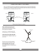
3. Remove all utensils and food from cooktop. 4. Wipe up heavy soil on the oven bottom. 5. Clean spills on oven front frame (A) and the oven door outside of the gasket area (B) with a damp cloth. These areas are outside the self cleaning area and soil will become baked on. A-oven front frame Do not clean gasket B-outside oven door gasket area DO NOT under any circumstance use a commercial oven cleaner, or surface coating for ovens on a self clean oven. This will damage the finish.
"P 1.30" and "AUTO lights up when self clean is activated display will show time, 1:30 to start, adjustable to 3:00 hours maximum press "+" to increase self clean time press bake button to set self clean mode How to Self Clean Figure A - Control Panel Layout The recommended self clean time is 3 hours. The cycle can be set however, anywhere from 1 hour 30 minutes for light soiling, to 3 hours maximum for heavy soiling. Be sure the self clean safety instructions have been followed. 1.
5. Turn the oven thermostat control knob clockwise until c). Bake indicator it can no longer be turned (see will come on. Self Clean position 6. Your oven is now in the self clean mode and will operate in self clean mode for the time you have set. 7. At the end of the cycle the oven will shut off and the "P0.00" and the symbol "AUTO" clock will alternately. 8. Turn the thermostat control knob to “0”. The clock will until the oven is unlocked.
5. Next, press the " of day. STOP end time button, the display will change to show the time 6. Use the " " or " " to set the actual time of the day you want the oven to shut off. After 5 seconds the display will change to show self clean time remaining, the "AUTO" indicator will remain lit, and the " " symbol will shut off showing the oven is not in operation and delay timer is active. 7. Turn the oven thermostat control knob, to the self clean position. (see previous page) C, 8.
Nickel Plated Trim Nickel plated surfaces may be cleaned with any non abrasive chrome and metal polish (such as Flitz) or Windex and a soft cloth. If any acid based food or liquid, such as lemon juice or tomato juice, is spilled on the range, wipe it at once to prevent staining. Exhaust Hood An exhaust filter is included with your exhaust hood. The filter may be cleaned periodically in soapy water. The filter should be replaced every 4 months or when they begin to restrict air flow.
Interior Oven Rack The oven rack is designed with stop-locks so that when placed correctly on the supports, it (a) will stop before coming completely out of the oven, (b) will not tip when placing or removing food.
Removal of Oven Door At times you may want to remove the oven door for thorough cleaning of the oven. Removal of the oven door is easy: 1) Open oven door, and latch the brass catches on to the upper leg of the hinge. (see below). Make sure the catch is securely hinged. 2) With a hand on each side of the door lift the door slightly, and pull out. 3) The door weighs about 39 LBS (18 kg) , please exercise caution when removing the door. 4) To replace the door reverse this sequence.
Warming Drawer These ranges are equipped with a warming drawer below the main oven. They have a variable thermostat, which is on the right side behind the drawer front. When "ON", a light will be visible on the control panel cooktop. When removing the drawer ensure that the control is set to "0" (the off position) and the drawer is cool. To remove the drawer, open the drawer until you see a plastic clip on the side of the track attached to the drawer.
Range Problem Solver Oven light does not work • Check that light switch is not jammed. The light switch activator is located at the left side bottom of the oven door.(to inspect: remove door as per page 36 instructions) To save time and money before you call for service, check this guide. If you have a problem it may be minor. You may be able to correct it yourself. Use this Guide to locate your problem and then follow the suggested recommendation. • Light bulb is loose.
HEARTLAND Model 6210 / 8210 Electric Self Clean Range Parts Chart ® A P P L I A N C E S 1595 60285 60288 1609 1588 1600 3599 1592 60283 60287 1556 60286 60605 65 22 6677 1551 6881 66 76-48" 6659 60226 60504 60521 (warming) 6166 6663 60327 60277 (oven) 60502 1125 60238 60522 60503 60520 80144 60309 60505 6660 6198 60250 6662 60251 60501 60277 1110 9234 6197 60252 6661 60510 2 x 8 202 3599 1600 80131 1592 8 200 1595 80142 820 4 1609 1588 80138 80132 6202 60604 60330 8
Model 6210 / 8210 Range Parts Chart TO ENSURE THE CORRECT COLOUR MATCH WHEN ORDERING COLORED PANELS, BOTH THE COLOR AND SERIAL NUMBER MUST BE PROVIDED.
L1 L2 N MODEL #8210 1 RED 1A S/C Technical Data N WHITE L BLACK RED/BLACK COOKTOP LIGHT CONVECTION FAN SWITCH WHITE/BLACK - Voltage 240 v / 60 Hz - Load 10.6 kW (model 8210) - Load 13.6 kW (model 6210) H EXHAUST MOTOR BLK BLUE M RD EXHAUST FAN SWITCH GREEN ORANGE RED WHITE NOTE: Service amperage should be calculated by a electrician.
1260 E. VanDeinse St. , Greenville , MI 48838 Toll Free Phone 1-800-223-3900 Fax (616) 754-9690 INSTRUCTIONS D’INSTALLATION ET D’UTILISATION POUR LES MODÈLES : 6210 Cuisinière électrique autonettoyante à convection (48 po) - surface en vitrocéramique 8210 Cuisinière électrique autonettoyante à convection (30 po) - surface en vitrocéramique À L’ATTENTION DE L’INSTALLATEUR : Laisser ce manuel avec l’appareil.
Déplacement de la cuisinière pour le service ou le nettoyage AVERTISSEMENT La cuisinière repose sur une base. Ne déplacez la cuisinière que par sa base. 1. Débranchez la cuisinière du courant électrique. 2. Posez une protection sur le sol devant la cuisinière. 3. Glisser la cuisinière en l’éloignant du mur et mettez la protection sous les pattes de devant. Continuez à tirer doucement jusqu’à ce que l’accès à l’arrière est libre.
Cuisinières électrique : Modèles 6210 Cuisinières électrique autonettoyantes : Modèles 8210 GARANTIE LIMITÉE D’UN AN POUR LE PRODUIT ENTIER AGA Marvel garantit, pour une période d'un an à partir de la date d’achat initial, le remplacement ou la réparation de toutes les pièces de la cuisinière, y compris les composants du système au gaz, qui présententent un vice de matériau ou fabrication, à l’exception des surfaces peintes ou finies en porcelaine émaillée et des surfaces plaquées.
TABLE DES MATIÈRES Description Page 1. Assemblage et installation ......................................... 2 Description Page 27. Conseils de cuisson au four ...................................... 27 2. Positionnement de la cuisinière ................................. 6 28. Guide pour le rôtissage/grillage des viandes ............ 28 3. Dégagements d’installation ........................................ 6 29. Conseils de cuisson au four et de rôtissage ............. 29 4. Hotte à évacuation .........
Assemblage et installation Nota : y en aurait eu, avisez votre détaillant immédiatement ! Mise en garde pour le désemballage : ne pas soulever l’appareil par la garniture en nickel, mais seulement par la base! Désemballage : Nota : pour éviter des lésions, portez des lunettes de sécurité et et des gants de protection lors du déballage. 1) Dévissez les 12 vis qui tiennent la caisse sur la palette. Il y a 12 le long du fond et de 4 le long du dessus.
Vis de tôlerie Rondelle en acier DE S SU IÈRE S DE ISIN CU Vis d’assemblage Cornière Joint – Pelez la doublure et collez-le Rondelle en acier Vis de tôlerie Vis d’assemblage (Noire) (Nickelée) Joint - Quand vous manœuvrez le placard n’oubliez pas qu’il est très lourd. Utilisez votre main pour le soutenir durant son installation. - Placez la boîte sur le sol près de la cuisinière (voir la Figure 1 en page 2).
Arrière de l’appareil Adaptateur d’évacuation de 3-1/2" x 10" (8,9 x 25,4 cm). Vis de tôlerie avec 4 vis de tôlerie. Si votre ventilation débouche à l’extérieur d’évacuation de 3-1/2" x 10" avec 4 vis de tôlerie. Fixez votre conduit d’évacuation sur cet adaptateur. La petite boîte contient : - ensemble de visserie - adaptateur d’évacuation de 3-1/2" x 10" Remarque : La longueur maximale de tronçon d’évacuation est de 25 pieds (7,6 m).
RACCORDEMENT DE L’ALIMENTATION SUR LA CUISINIÈRE Après que votre hotte d’évacuation ait été installée, la dernière chose restant à faire est l’arrière de la cuisinière, sous le couvercle métallique. Enlevez la vis maintenant le couvercle sur l’arrière de la cuisinière et déposez ce couvercle. Enlevez le serre-câble de la cuisinière, qui se situe au-dessus de l’emplacement du couvercle.
Positionnement de la cuisinière 1. 2. 3. Mise en garde : Il sera peut être nécessaire de soulever la cuisinière et de la faire glisser pour l’installer si le plancher est irrégulier ou en présence de larges rainures profondes. 4. Place les deux mains sur la garniture et pousser la cuisinière avec précautions en s’assurant qu’il n’y a pas de débris sur le plancher.
HOTTE À ÉVACUATION Votre cuisinière est munie d’une hotte à deux vitesses qui peut être ventilée à l’extérieur ou installée sans évacuation. connaître les prix et les instructions de commande, téléphoner à votre détaillant. Installation sans évacuation Votre appareil est prêt pour utilisation sans évacuation.
Installation avec évacuation, outils, matériaux et dimensions Outils requis pour installer la hotte : - Marteau - Tournevis à lame plate - Pinces - Perceuse électrique - Mèches de 3/32 po (3 mm) et 1/2 po (13mm) - Ruban à mesurer - Scie à découper OU scie à guichet Matériaux requis : - Conduit de 3 1/4 x 10 po (82.55 mm x 254 mm) - assez long pour traverser le mur ou le grenier vers l’extérieur. Nombre de coudes requis. Chapeau de ventilation ou prise de ventilation murale.
Importantes instructions de sécurité 1. INSTALLATION CORRECTE - ASSUREZ-VOUS QUE VOTRE CUISINÌERE EST INSTALLÉE CORRECTEMENT ET MISE À LA TERRE PAR UN TECHNICIEN QUALIFIÉ. Demandez à l’installateur de vous montre où se trouve le disjoncteur ou la fusible. Indiquez cet endroit d’une marque pour ne pas l’oublier. 2. Ne jamais utiliser votre cuisinière pour chauffer la pièce. 3. Ne pas laisser d’enfants seuls près de l’appareil lorsqu’il est utilisé.
sont graisseux. Évitez de chauffer un plat de cuisson vide, car cela pourrait endommager la table de cuisson ainsi que le plat. - Il n’est pas recommandé d’utiliser des plats de cuisson en verre ou en céramique avec votre table de cuisson radiante en verre céramique, car ils pourraient briser en raison du soudain changement de température. - Les poignées de plats de cuisson doivent être tournées vers l’intérieur et ne pas surplomber les autres unités de au contact accidentel avec le plat de cuisson.
- Lorsque la table de cuisson est refroidie, n’utilisez pas que le nettoyant de table de cuisson en céramique Cerama Bryte et le tampon de nettoyage Cerama Bryte pour nettoyer la table de cuisson. - Pour prévenir de possibles dommages à la surface de cuisson, n’appliquez pas de crème nettoyante à la surface en verre lorsqu’elle est chaude. - Après le nettoyage, utilisez un linge sec ou une serviette en papier pour enlever tout résidu de crème nettoyante.
Mesures de prudence pour l’autonettoyage Ne touchez pas les éléments chauffants ou les surfaces intérieures du four ; même lorsqu’ils sont de couleur sombre, les éléments chauffants peuvent être chauds. Les surfaces intérieures d’un four deviennent assez chaudes pour causer des brûlures. éléments chauffants ou les surfaces internes du four avant que ces derniers aient eu le temps de refroidir.
CARACTÉRISTIQUES - L'UTILISATION DES ÉLÉMENTS DE SURFACE Les boutons de commande de cuisson Modèle de 30 po Modèle de 48 po G G A A B C C B E A - 1200 watts, à chaleur radiante, dia. de 5 ½ po. B - 2000 watts, à chaleur radiante, dia. de 7 ½ po. C - 2500 watts, à double grandeur, à chaleur radiante, dia. de 9 po ; rond intérieur de 1000 watts. E -1500 watts, à chaleur radiante, dia. de 5 ½ po (modèle de 30 po seulement).
Comment régler les brûleurs Les brûleurs A,B, E et F: • Enfoncez les boutons et tournez les dans l’une ou l’autre direction selon le degré de chaleur que vous désirez. (Plus le numéro est élevé, plus également la chaleur est élevée.) • À basse (1) de même qu’à haute (7) température, le bouton de réglage émet un déclic en se mettant en place. • Le bouton de réglage ressort en émettant également un déclic lorsqu’on le tourne en position (0) pour éteindre.
La table de cuisson présente des éléments chauffants sous une surface lisse en céramique Euroreka. Note : Il est normal de sentir une légère odeur lorsqu’on utilise une table de cuisson neuve pour la première fois. L’odeur est causée par le chauffage des pièces neuves et de la matière isolante et elle disparaîtra en peu de temps. L’élément de surface s’allumera et s’éteindra alternativement, de façon à rester à l’intensité de chaleur que vous avez choisie.
Pour choisir le type de plat de cuisson : Les informations suivantes vous aideront à choisir des plats de cuisson qui conviennent bien aux tables de cuisson en vitrocéramique. Acier inoxydable : Recommandé. Aluminium : Aluminium lourd recommandé. Bonne conductivité. Des rayures d’aluminium pourraient apparaître parfois sur la table de cuisson, mais on peut les supprimer en les nettoyant immédiatement. Étant donné son point de fusion bas, l’aluminium léger ne convient pas. Fond en cuivre : Recommandé.
Nettoyage de la table de cuisson en vitrocéramique : (pour obtenir de l’information sur l’un quelconque des produits de nettoyage, veuillez vous reporter à la page 15) Nettoyez votre table de cuisson après chaque débordement Assurez-vous que tous les boutons de réglage sont à la position « 0 » (éteinte).
Nettoyage de la table de cuisson en vitrocéramique : Que faire en cas de débordements sucrés ? Nos tests montrent que si vous cuisez des aliments très sucrés, tels que de la gelée ou du fondant et que des débordements se produisent, il pourrait en résulter des dommages permanents à la surface de la table de cuisson sauf si vous nettoyez immédiatement le débordement. 1. Fermez tous les éléments de surface. Retirez tous les plats chauds. 2.
Caractéristiques Tableau de commande Boutons de commande de la cuisson Les boutons de commande de cuisson se trouvent du côté droit de la table de cuisson; ces boutons présentent un rend la cuisson de surface et au four plus aisée et précise. B Tiroir pour les ustensiles A Commandes des éléments et du four C Rangement H He ea ear ar rttla tla lan nd nd d D E Caractéristiques du four A) Commande de la température du four - avec commande de la cuisson et du grillage.
Tableau de commande I A U T O TIM ER STOP J L K Veuillez noter : le réglage de la minuterie n’affecte pas le tiroir chauffe-plat. Tableau de commande de l’horloge – La minuterie et le tableau de commandes sont dissimulés derrière de la porte de l'armoire pour les modèles standard et à autonettoyage. Note: Le tiroir chauffe-plat n'est pas commandé par la minutérie. I) Horloge numérique : Avec comte-minutes et déclenchement et arrêt automatiques de cuisson.
Fonctionnement et commande du tiroir chauffe-plat Pour allumer le tiroir chauffe-plat, trouvez d’abord la commande des températures, à côté du tiroir-réchaud, derrière la porte du tiroir. Sélectionnez une température, sur l’échelle allant de 0 à 3 et dans laquelle 0 correspond à une chaleur nulle et 3 à une chaleur élevée. La température varie de manière continue de 130°F à 220°F.
Commande de la cuisson au four et au grilloir Témoin lumineux du four principal Témoin lumineux du tiroir chauffe-plat Commande de la cuisson au four et au grilloir Cuisson au four Pour la cuisson au four, enfoncez la commande du four et tournez-la dans le sens des aiguilles d’une montre à la température que vous désirez. Lorsque vous allumez le four, le témoin lumineux du four sous le symbole de la cuisson au four s’allume en même temps que l’élément du four.
Utilisation du four Avant de commencer : 1. Enlevez les grilles et leurs supports du four et nettoyez-les à l’aide d’une eau savonneuse. (Voir comment enlever la grille du four et les supports de la grille à la page 36.) 2. Déballez la lèchefrite et nettoyez-la à l’aide d’une eau savonneuse. 3. Nettoyez le four à l’aide d’une eau savonneuse en vous assurant que tous les adhésifs ont été enlevés. 4. Réglez l’horloge.
Comment choisir les méthodes de cuisson Cuisson au four ordinaire : Pour la cuisson au four, tournez la commande du four à n’importe quelle température entre 150°F et 500°F (65°C et 290°C). Une fois cela fait, le témoin de la cuisson au four s’allumera ainsi que l’élément de sole dans le four. Préchauffez toujours le four de 5 à 10 minutes. Durant la cuisson, l’élément de sole s’allumera et s’éteindra alternativement pour maintenir la température choisie.
HORLOGE / MINUTERIE Le symbole de la cloche indique que le compteminutes fonctionne.
2. Annulation du compte - minutes a) Presser le bouton « ». b) Appuyer sur le bouton de réglage « » et remettre à zéro. c) Appuyer ensuite sur le bouton d’annulation « » Cuisson programmée (four principale seulement) 1. Réglage de la cuisson programmée : a) Si l’on désire la cuisson par convection, activer le commutateur à bascule du ventilateur commande en dessous de la minuterie. b) Appuyer sur le bouton « c) Utiliser les boutons « « » sur le tableau de »“ pour la durée de cuisson au four.
Conseils de cuisson au four Cuisson ordinaire et par convection Cuisson au four ordinaire : Il s’agit du mode traditionnel de cuisson à «chaleur radiante». Vous pouvez choisir cette méthode de cuisson pour les recettes que vous connaissez bien et avez déjà essayées. Comme c’est le cas avec tous les fours à chaleur radiante, il faut le préchauffer, surtout pour les pâtisseries. Votre recette indiquera normalement s’il faut préchauffer ou non.
Guide de cuisson Le présent tableau de référence ne devrait servir qu’à vous guider, car de nombreuses variables telles que la grosseur de l’aliment, la température et les goûts individuels peuvent affecter le temps de cuisson. Donnez, s’il y a lieu, plus d’importance à la recette ou aux directives sur le paquet. Prenez à chaque fois note de vos résultats ainsi que de vos températures et temps de cuisson préférés.
Guide pour le grillage : Guide de cuisson Le présent tableau de référence ne devrait servir qu’à vous guider, car de nombreuses variables telles que la grosseur de l’aliment, la température et les goûts individuels peuvent affecter le temps de cuisson. Donnez, s’il y a lieu, plus d’importance à la recette ou aux directives sur le paquet. Prenez à chaque fois note de vos résultats ainsi que de vos températures et temps de cuisson préférés.
Entretien et nettoyage Surface de cuisson vitrocéramique (Voir "Nettoyage de la table de cuisson en vitrocéramique", pages 17 et 18) Porcelaine et surfaces émaillées Pour garder propre La porcelaine et les surfaces émaillées sont d’entretien très facile et simple à nettoyer, mais, étant du verre, ne résistent pas aux mauvais traitements. Évitez les variations de températures extrêmes à la porcelaine. La porcelaine est du verre et des changements soudains de température pourraient l’amener à craquer.
3. Retirer de dessus la table de cuisson tous plats ustensiles et nourriture. 4. Enlever d’un coup d’éponge le plus gros des saletés qui tapissent le fond du four. 5. Nettoyez les éclaboussures sur la partie interne de la porte (A) du four et sur la partie de porte qui entoure le joint (B) avec un chiffon humide. Ces zones échappent à l’action auto-nettoyante et les graisses y cuisent et re-cuisent.
"AUTO” s’allume lorsque l’autonettoyage est activé. L’affichage indique le temps, en commencant par 1:30 jusqu’à 3:00 heures au maximum A U T O T IM E R S TO P Appuyer sur « + » pour augmenter le temps de l’autonettoyage Appuyer sur le boutom de cuisson au four pour activer l’autonettoyage Figure A - Disposition du tableau de commande Comment procéder à l’autonettoyage La durée recommandée pour l’autonettoyage est de 3 heures.
5. Tourner jusqu’à ce que ce ne soit plus possible le bouton de commande du thermostat dans le sens des Position d’autonettoyage de la cuisson au four s’allumera. 6. Votre four est maintenant en mode d’ autonettoyage et fonctionnera ainsi pour la dureé que vous avez choisi. et l’horloge clignotera et indiquera alternativement « P0.00 » et « AUTO ». 8. Tourner le bouton de commande du thermostat à « 0 ». L'horloge clignotera jusqu’à l’ouverture de la porte du four. 9.
3. Appuyer sur le bouton de cuisson « » sur l’hologe. » pour un temps d’autonettoyage supplémentaire par intervalles 4. Taper le bouton « d’une minute. Pour avancer le temps rapidement jusqu’à 3:00 heures au maximum, appuyez sur le bouton et tenez-le enfoncé. On recommande 3 heures pour le nettoyage maximal. 5. Appuyer ensuite le bouton « » 6. Utiliser le bouton « » ou « » pour régler l’heure actuelle de la journeé ou vous voulez que le four s’eteigne. Après 5 secondes, temps d’autonettoyage qui reste.
Hotte à évacuation commencent à obstruer le courant d’air. chez votre commerçant ou directement Vous pourrez vous procurer des chez Heartland Appliances. Veuillez en commander quatre ou plus à la fois pour réduire les frais de transport et de manutention. Reportez-vous aux instructions de la page 38 pour effectuer des commandes. accumulations de gras (qui pourraient causer des incendies) et nettoyez-le, selon ce qui est nécessaire, avec de l’eau et du savon.
Grilles du four La grille du four est munie de crans d’arrêt si bien que, lorsqu’elle est posée correctement sur les supports, elle (a) s’arrête avant de sortir complètement du four et (b) ne bascule pas lorsqu’on y met des aliments. Pour installer la grille, mettez les «pieds» de la grille sur les supports et poussez-la vers l’arrière lelong des supports (voir 1). Poussez la grille tout au fond du four jusqu’à ce qu’elle dépasse l’extrémité du support de la grille (voir 2).
Enlever la porte du four 1) Ouvrez la porte du four et accrochez les loquets en laiton aux pattes supérieures de la charnière (voir ci-dessous). Assurez-vous que les loquets sont bien accrochés. 2) Mettez une main de chaque côté de la porte, soulevez celle-ci légèrement et tirez. 3) La porte pèse environ 39 livres (18 kg) et il faut donc l’enlever avec précaution. 4) sont complètement engagées dans leurs réceptacles et que la porte est entièrement ouverte pour dégager les loquets de laiton.
Tiroir chauffe-plat Ces cuisinières sont munies, sous le four principal, d’un tiroir chauffe-plat pourvu, derrière le devant du tiroir, sur le côté droit, d’un thermostat variable. Lorsque le chauffe-plat est allumé, un témoin commande se trouve à « 0 » (la position d’arrêt) et que le tiroir soit refroidi. Pour enlever le tiroir, ouvrez le tiroir jusqu’à ce que vous puissiez voir des pinces en plastique sur le côté des coulisses du tiroir.
Guide de dépannage de la cuisinière La lumière du four ne fonctionne pas • Vérifiez que l’interrupteur ne soit pas coincé. L’activateur d’interrupteur de lumière se trouve à gauche et en bas de la porte selon les instructions de la page 37) Pour gagner du temps et économiser de l’argent, consultez ce guide avant d’appeler un technicien. Si vous avez un problème, il peut n’être qu’anodin et facile à régler par vous-même.
40
Schéma de pièces : Cuisinières électriques autonettoyantes Modèles 6210/8210 1595 60285 60288 1609 1588 1600 3599 1592 60283 60287 1556 60286 60605 65 22 6677 1551 6881 66 76-48" 6659 60226 60504 60521 (warming) 6166 6663 60327 60277 (oven) 60502 1125 60238 60522 60503 60520 6884 60309 60505 6660 6198 60250 6662 60251 60501 60277 1110 9234 6197 60252 6661 60510 2 x 8 202 3599 1600 80131 1592 8 200 1595 80142 820 4 1609 1588 80138 80132 6202 60604 60330 80149 1556 155
Liste de pièces pour cuisinières - modèles 6210 / 8210 60243 60244 60245 60250 60251 60252 60254 60260 60266 60277 60283 Panneau moulé, tiroir pour les ustensiles Devant du réservoir Panneau moulé du réservoir, (préciser la couleur) Patte d’assise Base d’assise (en Nickel) avant (48 po) Base d'assise latérale (30/48 po) Base d’assise (noir) - arrière (48 po) Plaque-couvercle des commandes (non illustr.