260 E. Van Deinse St. Greenville , MI 48838 Toll Free Phone 1-800-223-3900 Fax (616) 754-9690 www.heartlandapp.com MODEL 9200/7200 GAS RANGE Installation and Operating Instructions WARNING: Improper installation, adjustment, alteration, service or maintenance can cause injury or property damage. Refer to this manual. For assistance or additional information, consult a agency, manufacturer (dealer). Please read these instructions thoroughly before attempting to install this unit.
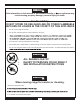
WARNING If the information in this manual is not followed exactly, a or explosion may result causing property damage, personal injury or death. For Your Safety DO NOT STORE OR USE GASOLINE OR OTHER FLAMMABLE VAPOURS OR LIQUIDS IN THE VICINITY OF THIS APPLIANCE • Do not use the range as a heater. • Do not heat unopened glass or metal containers in the oven. • . • • Avoid the use of aerosol containers near the range.
WARNING WHAT TO DO IF YOU SMELL GAS!! • Do not try to light any appliance. • Do not touch any electrical switch; do not use any phone in your building. • Immediately call your gas supplier from a neighbour’s phone. Follow the gas supplier’s instructions. • If you cannot reach your gas supplier, call the fire department. Installation and service must be performed by a qualified installer, service agency or the gas supplier. WARNING Never use the appliance as a space heater to heat or warm the room.
Gas Models 9200/7200 CONSUMER WARRANTY ENTIRE PRODUCT – LIMITED ONE YEAR WARRANTY AGA MARVELwarrants the replacement or repair of all Parts, including gas components of this stove which prove to for one year from the date of original purchase. Such parts will be repaired or replaced at the option of Aga-Heartland without charge, subject to the terms and conditions set out below. TERMS AND CONDITIONS 1.
TABLE OF CONTENTS Page Warning Positioning the Range Electrical Installation Exhaust Hood Ventless Installation Vented Installation Installation of Ducting Venting Safety Guidelines Gas Line Installation Clearance Diagrams Important Safety Instructions Exhaust Hood Safety Features Cooking Controls Oven Features Other Features Control Panel Layout Operation Top Burner Operation Oven Cooking & Lighting Range Thermostat Power Failure Operation Manually Lighting the Top Burner Manually Lighting the Oven Burner
Assembly and Installation To fully enjoy your new range, it is important that you read this booklet thoroughly. shipping damage, inform your dealer immediately! Caution when unpacking: Lift the range by the bottom skirt, do not lift by nickel trim. Unpacking: Note: to avoid injury, please wear safety equipment, glasses and gloves, while you are unpacking your new range. 1) Unscrew the 20 screws that hold the crate onto the skid. There are 12 along the bottom and 8 along the top.
BLANK
Sheet metal screw Steel washer E OV T S P TO Machine screw Bracket Gasket - Peel off backing and stick on. Steel Washer Sheet metal screw (black) Nut Machine screw (Nickel Plated) Gasket -Remember when working with the closet, the closet is top heavy . Use your hand to support it during installation. -With a helper,lift closet assembly from box by area that is circled. (See Fig.1 Page 2).
Back of closet Sheet metal screw 3 1/2" x 10" Exhaust adaptor you are venting outside, attach the 3 1/2" x 10" exhaust adaptor with 4 sheet metal screws. Fasten your exhaust ducting to the adaptor. Small box contains: - 3 1/2"x10 exhaust adapter ( not included with woodstove closets.) Note: maximum run of ducting is 25 linear feet (subtract 5' per 90 deg elbow added to the exhaust line and 2.5' per 45 deg elbow.
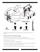
Back of stove Back of stove Power In (male receptacle) Exhaust Hood In (female receptacle, from closet ) Power In (male receptacle) Exhaust Hood In (female receptacle, from closet ) Model 9200 Model 7200 Positioning the Range 1. When the range is fully assembled, recheck all electrical connections especially between the exhaust hood and the back of the range. As well, check that all nuts and bolts have been tightened. 2. Ensure teflon gliders and flooring are clean. 3.
Electrical Installation THE MODEL 7200/9200 GAS RANGE MUST BE ELECTRICALLY GROUNDED IN COMPLIANCE WITH LOCAL CODES AND IN THE ABSENCE OF LOCAL CODES, WITH THE NATIONAL ELECTRICAL CODE ANSI/NFPA 70 “LATEST EDITION” IN THE U.S. OR THE CANADIAN ELECTRICAL CODE, PART I, CSA STANDARD C22.1 IN CANADA or YOUR NATIONAL ELECTRICAL CODE. Connect the female end of the power cord to the main power (male) receptacle at the rear of the stove. See Page 8 for receptacle locations and Figure 2 for receptacle illustration.
Ventless Installation Figure 4 Exhaust venting options Vented Installation, Tools, Material, and Dimensions Tools required to install vented hood: Hammer Slot screwdriver Pliers Electric drill Measuring tape Drill bits Sabre saw OR Keyhole saw Materials Required: Duct—enough to go through wall or attic to outside. Elbows as required.
Installation of Ducting Installation through an outside wall range hood outlet (see Figure 4, Page 10), making sure no wall studs are cut. Push range into position. From outside of the house, measure distance from the siding to the range outlet. Cut duct pipe that length, plus 1” (25mm) for overlap into outlet. Mechanically attach vent hood to pipe. Caulk the back of vent hood and around pipe where it goes through wall and into range hood outlet so caulking seals against outside siding.
Venting Safety Guidelines Installation must be done in accordance with all local and national codes. Use only materials which conform to local codes in effect. Be sure power is disconnected before doing any electrical work. All duct work must be metal and mechanically fastened. Do not use plastic duct. The range hood should never be exhausted into a wall cavity or an attic where an accumulation of grease could become a fire hazard.
Model 9200 in the US or in Canada with the Canadian Electrical Code, Part I, CSA Standard C22, or the Local National Electrical Code. Appliances Venting How to Steps Appliance Clearances (see Page 15 for additional details): • Sides of stove to adjacent surfaces: 1/2” (1.
Model 9200 Dimensions 3-7/8” (10 cm) cresting panel 27-1/2” (70 cm) Range HoodOutlet 3 1/4” x 10” 8 cm x 25 cm 13-3/4” (35 cm) 11-3/8” (29 cm) 13” 33cm 56” (142 cm) Gas Inlet-1/2” NPT 66-1/4” (168 cm) 62-3/8” (159 cm) 36-1/8” (92 cm) 36-1/8” (92 cm) Power Cord 34” (86 cm) 28” (72 cm) 29-3/4” (76 cm) 3-3/4” (10 cm) Exhaust Hood (female) Receptacle 62-3/8” (159 cm) 29-3/4” (76 cm) Figure 9 Range Hood Outlet 3-1/2” x 10-1/2” (8.9 cm x 26.7 cm) 30” (76 cm) Rough in Measurements .
Model 7200 in the US or in Canada with the Canadian Electrical Code, Part I, CSA Standard C22, or the Local National Electrical Code. Appliances How to Steps Venting Appliance Clearances (see Page 17 for additional details): • Sides of stove to adjacent surfaces: 1/2” (1.
Model 7200 Dimensions 3-7/8” (10 cm) Cresting Panel 37-3/4” (96 cm) Range Hood Outlet 3-1/4” x 10” (8cm x 25cm) 11-3/8” (29 cm) 56” (142 cm) 62-3/8” (159 cm) 36-1/8” (92 cm) 4-3/4” (12 cm) 36-1/8” (92 cm) 30” (76 cm) 28” (72 cm) 39-3/4” (101 cm) 20” (51 cm) 13” 33cm. Gas Inlet 1/2” NPT 66-1/4” (169 cm) Power Cord Exhaust Hood (female) Receptacle 39-3/4” 47-1/2” (101 cm) (121 cm) Figure 11 Rough in Measurements Range Hood Outlet 3-1/2” x 10-1/2” (8.9 cm x 26.
Important Safety Instructions 1. PROPER INSTALLATION—BE SURE YOUR APPLIANCE IS PROPERLY INSTALLED AND GROUNDED BY A QUALIFIED TECHNICIAN. 2. NEVER use this appliance as a space heater to heat or warm the room. Doing so may result in Carbon Monoxide poisoning and in overheating of the oven. 3. Do not leave children alone. Children should not be left alone or unattended in area where appliance is in use. They should never be allowed to sit or stand on any part of the appliance. 4. 5. 6. cabinet. 7. . 8.
Features I A D B C L E F H Figure 13 G Cooking Controls The cooking controls are located on the right hand side of the cooktop; these controls of settings for ease and accuracy in cooking and baking. Sealed Burner Features (See Figure 13) A) Centre Burners - are two maximum 8,000 BTU (2.34 kW)(L/P 7,000 BTU) with simmer of 600 BTU (.2 kW) sealed gas burners, easy clean, for medium duty cooking tasks. B) Right Burners (48” models only) - front sealed burner is maximum 10,000 BTU (2.
J A U T O T IM E R S TOP M K Figure 14 Oven Features f! F) Gas Oven Features: -4 position racking -16,500 BTU (4.83Kw) oven burner G) Broiler - Broiler drawer located under the oven, glides open for easy access for all your broiling needs. H) More Storage - (model 7200 only) open the rack storage door to gain access to more storage area. Other Features (See Figure 14) I) Closet Door - the minute minde r, exhaust fan control and overhead light switch are concealed behind the closet door.
Control Panel Layout The control panel is laid out in a straight line and each control is identified by a graphic on the right side of the knob.
Operation Top Burner Operation Lighting the Top Burners Your range is equipped with a spark ignition system that is electrically operated. You need only to push in and turn the knob to any position and the burner will light. When you turn the knob, you will hear a distinct clicking noise. After the burner lights, the clicking noise will stop. Note: when lighting any one burner, all burners will spark, but only the burner that you have selected will light.
Oven Cooking Oven Lighting to keep oven knob depressed for 5-6 seconds after the oven ignition has occurred. The extra 5-6 seconds is toheat up the All units feature igniting procedure may have to be repeated 2-4 times to push out any air in the gas lines. does not light in 5-6 seconds, STOP. Release oven knob, this will prevent any further gas from going into the oven. Wait at least 1 minute before trying to light oven again. If you are still not successful see “trouble shooting guide”.
Power Failure Operation If electrical power is interrupted in your area, you can still cook meals on your Heartland gas range. By following these . Caution: make sure your hands and clothing are clear of the burner you are lighting! Top Burner Control Manually Lighting the Top Burners 1) Remove cast grate for unobstructed access to the burner head. 2) 3) Push in and turn the corresponding control knob to the medium setting. 4) e.
Clock / Timer Figure 20 Minute Minder Adjust Setting Up Bell symbol indicates minute minder in operation Adjust Setting Down Functions: Reset minute minder Power on Display is flashing Press " Set time of day Signal The signal after time out will stay on 7 min- Press left button" and " " and " release " ". Set time of day with " " " buttons.
Cooking Guide Heartland 7200/9200 Cooking Guide Food Meat Roasting Guide Whole Chicken Chicken Wings Fish Roast Lamb Turkey - unstuffed Turkey - stuffed Food Temp (°F) Time Rack Position 375 °F 350 °F 350 °F 325 °F 325 °F 325 °F 325 °F 40 min/lb 20 min 20 min 35 min/lb 35 min/lb 12-16 min/lb 15-18 min/lb 3rd 4th 2nd 2nd or 3rd 2nd 2nd 2nd Temp (°F) Time Rack Position Broil Broil Broil 10-15 min 30 min 20 min Broil Drawer Broil Drawer Broil Drawer Broiling Guide Steak Chicken Breast Pork Ch
Care and Cleaning CAUTION: When cleaning the cooking surface around the valve stems, be aware that detergents may corrode the electrical contacts on the valve switches (preventing an ignition spark) and may also degrade the gasket seal on the valve itself (causing a gas leak). Porcelain Keeping it clean The porcelain is very serviceable and simple to clean, but because it is glass, it will not withstand rough handling or abuse. Never clean porcelain parts while stove is hot.
Oven Cleaning Your range must be kept clean and free of accumulations of grease or spillovers which may ignite. This is most important in the oven and broiling compartment. When cleaning the oven, make sure it is turned “Off” and is cool. For simple spills, clean the oven with a strong solution of detergent, then wipe with a clean damp cloth and dry. When food or grease has burned on the oven lining, apply a strong oven cleaning compound. Follow directions destroy the oven door seals or plated surfaces.
Nickel-Plated Trim Nickel must be cleaned with warm soapy water and a micro cloth. If any acid-based food or liquid, such as lemon juice or tomato juice, is spilled on the range, wipe it at once to prevent staining. Exhaust Hood An exhaust filter is included with your exhaust hood. The filter may be cleaned periodically in soapy water. The filter should be replaced every 4 months or when they begin to restrict air flow. Extras are available from your dealer or directly from Aga-Heartland.
Interior Oven Rack Removal The oven rack is designed with stop-locks so that when placed correctly on the supports, it (a) will stop before coming completely out of the oven, (b) will not tip when placing or removing food. To install, place the rack “feet” on the rack support and push the oven rack backward along the rack support. (See Push the oven rack all the way to the back until the oven rack slips off the end of the rack support.
Removal of Oven Door At times you may want to remove the oven door for thorough cleaning of the oven. Removal of the oven door is easy: 1) Open oven door, and latch the brass catches on to the upper leg of the hinge. (See below). Make sure the catch is securely hinged. 2) With a hand on each side of the door lift the door slightly, and pull out. 3) The door weighs about 25 lbs (11 kg), so exercise caution when removing the door. 4) To replace the door reverse this sequence.
Broiling Broiling is cooking by direct radiated heat from above the food. It is fast because no preheat time is required and the food is close to the burner. When broiling, the oven control knob should be set to the broil symbol or the 500°F (265°C) setting on the knob. The broiler oven drawer should be left open 3 inches during broiling to allow the burner to stay on to it’s highest position. This allows you to keep an eye on your food.
Setup and Trouble Shooting Timer Timer Exhaust Fan Speed Control Light Switch Filter Filter Splashback Burner and Oven Controls Splashback Exhaust Fan Speed Control Light Switch Burner and Oven Controls Oven Light Oven Light Broil Drawer Broil Drawer 9200 Rack Storage Drawer Figure 27 7200 Burner Setup & Adjustment installed. You should check the following: i) First check to make sure there are no gas leaks.
Air Shutter Adjustment (oven burner only) (10.6mm). (See Figure 29) Reduce the shutter opening if: • • is not burning all the way around • is noisy like a small blow torch. Increase the shutter opening if: • Air Shutter Adjustment Figure 29 • there is no sharp blue cone • soot appears on the bottom of cooking pans. The air shutter is adjusted by loosening the locking screw and rotating the shutter to allow more or less air into the tube.
Trouble Shooting Guide FOR ALL BURNERS EQUIPPED FOR REIGNITION WITH " AUTO RE-IGNITION " Problem Cause Remedy A. Spark Ignition No power to spark module - module switch faulty. Check electrical supply to spark module with voltmeter replace module. 2. No sparks when one or some control knob(s) is (are) turned to “light”. Reignition electrode controlled by knob switch is grounded or has a high resistance leak.
Conversion Kits and Information Normally, Model 7200 and 9200 are ordered from the factory preset for either Natural Gas or Liquid Propane. However, they can be converted after installation by performing a conversion procedure to the gas components with the appropriate conversion kit. The components requiring conversion are, 1) the pressure regulator, 2) top burner controls, 3) oven burner control, 4) the top burners 5) oven burner Kits can be ordered from your dealer or directly from AGA Marvel.
36
7200/9200 Parts Diagram 1600 1595 60285 1588 60288 1609 1588 60283 60287 1556 60286 60605 1551 7374 6659 6676 6663 60226 60504 60521 60316 6660 7162 60277 6662 7161 60502 1125 60238 60503 60520 7797 8202 60522 6661 8200 60505 6884 60250 60251 60501 60277 60604 60252 1110 60510 7720 1600 80131 1588 1595 80138 80132 1588 med. lrg. 80142 1609 80149 1556 7794 1551 80141 7599-#9200 7793-#7200 7372 80128 7162 60502 7161 lrg. med. 60277 1125 60238 lrg. med.
Model 7200/9200 Range Parts List TO ENSURE THE CORRECT COLOUR MATCH WHEN ORDERING COLORED PANELS, BOTH THE COLOUR AND SERIAL NUMBER MUST BE PROVIDED.
Serial No. HLG00001 HLG00001 HLG00001 AGA MARVEL 1260 E. Van Deinse, Greenville , MI 48838 Model 7200/9200 Serial No. HLG00001 Natural Gas 8000 BTU/HR 10000 BTU/HR 16500 BTU/HR 5 IN. W.C. 120 Volt 3 amps. 60 Hz Medium Large Oven Manifold Pressure Power Requirements LP/Propane 7000 BTU/HR 9000 BTU/HR 16500 BTU/HR 10 IN. W.C. This appliance can be used with LP/Propane gas and Natural gas. The gas appliance regulator must be set for the gas with which the appliance is used.
Wiring Diagrams Technical Data - Voltage 120 v / 60 Hz - Load 3 amps (model 9200) - Load 3 amps (model 7200) NOTE: Service amperage should be calculated by a qualified electrician. The maximum propane/natural gas supply inlet must not exceed 14 inches of water column. The minimum gas supply inlet should be at least 5 inches of water column for natural gas or at least 11 inches of water column for LP gas. Gas services should be checked by a qualified gas technician.
1260 E. VanDeinse St. Greenville , MI 48838 Toll Free Phone 1-800-223-3900 Fax (616) 754-9690 INSTRUCTIONS D’INSTALLATION ET D’UTILISATION POUR LES MODÈLES : MODÈLE 9200/7200 CUISINIÈRE À GAZ Avertissement : Une installation, un ajustement, une modification, un service ou un entretien impropre peut causer des blessures ou des dommages. Se référer à ce manuel. Pour de l’aide ou de l’information additionnelle, consulter un installateur qualifié, une agence de service, ou le manufacturier (détaillant).
Attention: Si les renseignements fournis dans ce manuel ne sont pas respectés à la lettre, un incendie ou une explosion peuvent en résulter, provocant ainsi des dégâts matériels, des blessures et même des décès. —POUR VOTRE SÉCURITÉ— Ne pas utiliser ou entreposer d’essence ou tout autre produit inflammable à proximité de cet appareil. * Ne pas utiliser la cuisinière comme appariel de chauffage. * Ne pas chauffer de récipients fermés en verre ou en métal dans le four.
Attention: Si les renseignements fournis dans ce manuel ne sont pas respectés à la lettre, un incendie ou une explosion peuvent en résulter, provocant ainsi des dégâts matériels, des blessures et même des décès. QUE FAIRE LORSQU’ON SENT UNE ODEUR DE GAZ. • Ne pas essayer d’allumer d’autres appareils ménager. • Ne pas toucher aux prises électriques. Ne pas utiliserles appareils télephoniques de votre bâtiment. • Appeler immédiatement le fournisseur de gaz de chez les voisins. Suivre ses directives.
Modèles 9200/7200 à gaz GARANTIE DU CONSOMMATEUR GARANTIE LIMITÉE D'UN AN POUR LE PRODUIT ENTIER AGA-HEARTLAND garantit, pour une période d'un an à partir de la date d’achat initial, le remplacement ou la réparation de toutes les pièces de la cuisinière, y compris les composants du système au gaz, qui présententent un vice de matériau ou fabrication, à l’exception des surfaces peintes ou finies en porcelaine émaillée et des surfaces plaquées.
TABLE DES MATIÈRES 1. Montage de la hotte d’évacuation 2. Positionnement de la cuisinière 3. Dégagements d’installation 4. Installation électrique 5. Hotte d’évacuation 6. Installation sans évacuation 7. Installation ventilée 8. Installation du conduit 9. Directives de sécurité pour l’évacuation 10. Installation de la conduite de gaz 11. Schéma des Dégagements 12. Instructions importantes de sécurité 13. Sécurité de la hotte d’évacuation 14. Caractéristiques 15. Cuisine Des Commandes 16.
Montage de la hotte d’évacuation à la cuisinière Voir le manuel intitule "Instruction d’assemblage du cabinet pour les cuisinières à gaz, électriques, mixtes et à bois" inclus avec le cabinet. Figure 1 Positionnement de la cuisinière 1. Lorsque la cuisinière est complètement assemblée, revérifier toutes les connexions élec triques spécialement entre la hotte d’évacuation et l’arrière de la cuisinière. Vérifier aussi que tous les boulons et les écrous sont bien serrés. 2.
Dégagements d’installation C’est important d’avoir une bonne circulation d’air, si la cuisinière doit être à côté du réfrigérateur, il doit y avoir au moins 5 po d’espace entre les deux. Ne pas installer la cuisinière plus près que 1/2 po des surfaces adjacentes. L’installation du cabinet de rangement au-dessus de la surface chauffante devrait être éviter afin d’éliminer les risques de brûlures ou d’incendies. S’il y a déjà un cabinet, ayez au moins 30 po de dégagement. (Voir fig. 3.
Installation électrique LA CUISINIÈRE À GAZ MODÈLE 7200/9200 DOIT ÊTRE MISE À LA TERRE CONFORME AUX CODES LOCAUX, OU DANS L’ABSENCE DES CODES LOCAUX, AU CODE ÉLECTRIQUE NATIONAL ANSI/NFPA 70 “ÉDITION RÉCENTE” AU É.-U OU LE CODE ÉLECTRIQUE CANADIEN, PARTIE 1, LA NORME CSA STANDARD C22.1, AU CANADA, OU LE CODE ÉLECTRIQUE NATIONAL. Brancher le bout femelle du câble d’alimentation à la prise principale (mâle) à l’arrière de la cuisinière.
Hotte d’évacuation Votre cuisinière est munie d’une hotte à deux vitesses qui peut être ventilée à l’extérieur ou installée sans évacuation. Un jeu de filtres est inclus avec votre hotte. Les filtres doivent être nettoyés périodiquement dans une eau savonneuse. Des filtres supplémentaires sont disponibles chez votre détaillant ou directement chez Aga-Heartland Inc. Veuillez commander 4 filtres ou plus à la fois pour économiser sur les frais de manutention et de transport.
Installation du conduit Installation à travers un mur extérieur Retirer le déflecteur d’air (utilisé avec une hotte sans évacuation seulement). Découper une ouverture appropriée dans le mur directement derrière la sortie de la hotte de la cuisinière (voir figure 5, page 9), en vous assurant de ne pas couper les montants du mur. Pousser la cuisinière en position. De l’extérieur de la maison, mesurez la distance entre le revêtement et la sortie la cuisinière.
Directives de sécurité pour l’évacuation L’installation doit se conformer à toutes les exigences des codes locaux et nationaux. N’utiliser que des matériaux qui sont conformes aux codes locaux en vigueur. S’assurer que l’alimentation électrique est débranchée avant d’effectuer un travail électrique quelconque. Tous les conduits doivent être en métal. Ne pas utiliser de conduits en plastique.
Modèle 9200 Comment- aux étapes APPARIELS MISE A L’AIR LIBRE Degagements D'appariels (voir la page 13 pour les détails additionnels): • Les cotes de la cuisinieres et les surfaces adjacentes: 1/2 pm (1.
Modèle 9200 Dimensions 3-7/8” (10 cm) Panneau Se élevant à la crête 27-1/2” (70 cm) Sortie de la hotte 3 1/4” x 10” 8 cm x 25 cm 13-3/4” (35 cm) 11-3/8” (29 cm) 14” (36 cm) 56” (142 cm) 29-1/2” (75 cm) Entree de gaz-1/2” NPT 66-1/4” (168 cm) 62-3/8” (159 cm) Puissance absorbee 36-1/8” (92 cm) 36-1/8” (92 cm) HottePuissance absorbee (prise femelle) 43-3/4” (111 cm) avec porte with la oven 0”0”clearance Degagement de open four door back ouvrez-vous to thearriere 3” (7.
Modèle 7200 APPARIELS MISE A L’AIR LIBRE Comment- aux étapes Degagements D'appariels (voir la page 15 pour les détails additionnels): • Les cotes de la cuisinieres et les surfaces adjacentes: 1/2 po (1.5 cm) min • Le garniture en nickel sur les surfaces adjacentes: 0 po droit et 1po (2.
Modèle 7200 Dimensions 3-7/8” (10 cm) Panneau Se élevant à la crête 37-3/4” (96 cm) 11-3/8” (29 cm) Sortie de la hotte 3-1/4” x 10” (8cm x 25cm) 56” (142 cm) 62-3/8” (159 cm) 36-1/8” (92 cm) Puissance absorbee 36-1/8” (92 cm) 39-3/4” (101 cm) 14” (36 cm) 4-3/4” (12 cm) Entree de gaz-1/2” NPT 30” (76 cm) 28” (72 cm) 20” (51 cm) 29-1/2” (75 cm) 66-1/4” (169 cm) 43-3/4” (111 cm) avec porte withlaoven de four door open ouvrez-vous Hotte- Puissance absorbee (prise femelle) 39-3/4” 47-1/2” (101
INSTRUCTIONS IMPORTANTES DE SÉCURITÉ 1. INSTALLATION CONVENABLE - ASSUREZ-VOUS QUE VOTRE APPAREIL EST CONVENABLEMENT INSTALLÉ ET MIS À LA TERRE PAR UN TECHNICIEN QUALIFIÉ. 2. N’utilisez JAMAIS le présent appareil pour le chauffage, même d’appoint, de la pièce ou de la maison, car cela pour rait provoquer l’empoisonnement d’un être vivant au monoxyde de carbone ou la surchauffe de la cuisinière. 3. Ne pas laisser les enfants seuls.
Caractéristiques I A D B C E F H Figure 13 G Cuisine Des Commandes Les commandes de cuisson sont situées sur le côté droit de la surface de cuisson; ces commandes permettent de régler la température à l’infini pour une cuisson facile et précise. Caractéristiques des brûleurs scellé (Voir fig. 13) A) Brûleurs du centre : deux brûleurs à gaz scellés de 8000 BTU (2.34 kW) avec mijotage de 600 BTU (0,2 kW), pour des tâches moyennes de cuisson, faciles à nettoyer.
J L K M Figure 14 Caractéristiques du four E) Commande de la température du four - offrent une sélection infinie de températures de cuisson et de grillage. Tous les appareils sont équipés d'un dispositif de "coupure automatique du gaz", c’est-à-dire que si la flamme s’éteint pour une raison ou une autre, l'alimentation de gaz au brûleur du four s'arrête! F) Four au gaz: - 4 positions pour les grilles - zone de cuisson énergétiquement efficace 2 pi. cu. (.
Disposition du Tableau de Commande Le tableau de commande a une disposition rectiligne et chaque commande est identifié par un dessin sur le côté droit de bouton.
Utilisation Fonctionnement des bruleurs Allumage des bruleurs de la table de cuisson La table de cuisson est dotée d’un système électrique d’allumage par étincelles. Afin d’allumer le brûleur, pousser et tourner le bouton d’allumage. Peu importe la position à laquelle il se trouve. Lorsque la manette est tournée, une série de déclics se font entendre. Ils s’arrêteront aussitôt que le brûleur est allumé. Note : Lorsqu’on allume l’un des brûleurs, des étincelles jaillissent dans tous les autres.
Cuisson du four Allumage du four Ouvrez la porte du four: sur le fond, deux orifices vous permettront de voir la flamme du four après l’allumage. Enfoncez le bouton de réglage du four, puis, tout en le gardant enfoncé, sélectionnez la température de cuisson au four que vous souhaitée. Vous êtes censé entendre alors des jets d’étincelles jusqu’à l’apparition de la flamme. Après l’apparition de celle-ci, maintenez le bouton enfoncé pendant 5 ou 6 secondes.
Utilisation lors d’une panne d’électricité Même lors d’une panne d’électricité, vous pourrez vous servir de votre cuisinière à gaz de Aga-Heartland. En appliquant les directives simples suivantes, vous pourrez utiliser les brûleurs et le four, mais sans les avantages de l’électricité.
Horloge / Minuterie Figure 20 Compte-Minute Ajustez L'Établissement Le symbole de Bell indique le Compte-Minute en fonction Fonctions : NOTA : L’horloge doit être réglée, sinon le four ne fonctionnera pas ! Ajustez Établir Pour annuler le compte-minutes Poussez les boutons “ relâcher le “ Avec courant L’affichage clignote Appuyer sur le bouton de gauche “ ” en premier. ” et " pas été réglée avec le bouton “ touche). ” (seulement une ".
Guide Du Cuisson Heartland 7200/ 9200 Guide du Cuisson Guide de Torréfaction de Viande Nourriture Poulet Entier Ailes de poulet Poisson Rôtis Agneau Turquie - Non Bourrée Turquie-Bourré Temp (°F) 375°F 350°F 350°F 325°F 325°F 325°F 325°F Temps 40min/po 20min 20min 35min/po 35min/po 12-16min/po 15-18min/po Position De Support 3rd 4th 2nd 2nd ou 3rd 2nd 2nd 2nd Temps 10-15min 30min 20min Position De Support Tiroir De Grilleur Tiroir De Grilleur Tiroir De Grilleur Guide De Cuisson sur le gril Nourriture
Entretien et nettoyage ATTENTION : En nettoyant la surface à cuire autour des tiges de valve, rendez-vous compte que les détergents peuvent corroder les contacts électriques sur les commutateurs de valve (empêchant une étincelle d'allumage) et peuvent également dégrader le joint de garniture sur la valve lui-même (entraînant une fuite de gaz).
Nettoyage du four Garder la cuisinière propre, sans accumulation de graisse ou d’éclaboussures qui pourraient prendre feu. C’est très important pour le four et le compartiment de grillage. Avant de nettoyer le four, s’assurer qu’il est éteint et refroidi. Pour des petits déversements, nettoyer le four avec une forte solution de détergent, essuyer avec un linge humide propre et sécher. Lorsque des aliments ou de la graisse ont brûlé sur le revêtement du four, nettoyer avec un puissant détergent à four.
Garniture en nickel Du nickel doit être nettoyé avec l'eau savonneuse chaude et un tissu de mirco. Si on renverse n'importe quelle nourriture ou liquide à base d'acide, tel que le jus de citron ou le jus de tomates, sur la gamme, essuyez-l'immédiatement pour empêcher la souillure. Hotte d’évacuation Les filtres d’évacuation sont fournis avec votre hotte d’évacuation. On peut nettoyer périodiquement les filtres dans de l’eau savonneuse.
La Grille du four La grille du four est munie de crans d’arrêt si bien que, lorsqu’elle est posée correctement sur les supports, elle (a) s’arrête avant de sortir complètement du four et (b) ne bascule pas lorsqu’on y met des aliments. Pour installer la grille, mettez les «pieds» de la grille sur les supports et poussez-la vers l’arrière lelong des supports (voir 1 ). Poussez la grille tout au fond du four jusqu’à ce qu’elle dépasse l’extrémité du support de la grille (voir 2 ).
Enlevement de la porte du four Vous voudrez parfois enlever la porte du four afin de bien nettoyer le four. Rien n’est plus facile : 1) Ouvrez la porte du four et accrochez les loquets en laiton aux pattes supérieures de la charnière (voir ci-dessous). Assurez-vous que les loquets sont bien accrochés. 2) Mettez une main de chaque côté de la porte, soulevez celle-ci légèrement et tirez. 3) La porte pèse environ 17po (8 kg) et il faut donc l’enlever avec précaution.
Cuisson à l’élément de voûte (Grillage) La cuisson à l’élément de voûte consiste en la cuisson par irradiation de chaleur sur le dessus des aliments. Il s’agit d’une cuisson rapide n’exigeant pas de préchauffer le four et dans laquelle la nourriture se trouve près du brûleur. Pour cuire des aliments à l’élément de voûte, tournez le bouton de réglage du four au symbole de l’élément de voûte ou à la position 500.
Reglage Et Guide De Depannage Minuterie Minuterie Filtres Panneau Commande de vitesses de la hotte Interrupteur de la lumière Commande de vitesses de la hotte Interrupteur de la lumière Commandes des brûleurs et du four Filtres Panneau Commandes des brûleurs et du four Lumière du four Lumière du four Tiroir pour le grilloir Tiroir pour le grilloir 9200 tiroir de stockage en rayons Figure 27 7200 Montage et réglage des brûleurs La cuisinière a été soigneusement réglée et inspectée à l’usine, mai
Ajustement du volet d'air (brûleur du four seulement) La qualité de la flamme peut être changée en ajustant les volets d’air. Le réglage de la manufacture sur les volets d’air est 0,40 po (10.6 mm). (voir figure 29) Réduire l’ouverture de volet si: · la flamme semble vacillante · elle ne brûle pas tout autour · bruillant comme une petite lampe à souder. Augmenter l’ouverture du volet si: · la flamme a des bouts jaunes · il n’y a pas de cône bleu · de la suie apparaît en-dessous des casseroles.
Guide De Depannage Pour tous les bruleurs equipe du re-allumage avec “rectificateur de flamme” Probleme Cause Remedy A. L'allumage à étincelles L'allumeur ne reçoit pas de courant - l'interrupteur de l'allumeur est défectueux. Vérifier l'alimentation en courant de l'allumeur avec un voltmètre. Remplacer l'allumeur. L'électrode de réallumage contrôlée par le bouton d'allumage a une haute résistance ou bien est mise à la terre.
Information de Kit et Conversion Normalement, modelez 7200 et 9200 sont commandés du gaz naturel ou du propane de presetfor d’usine. Cependant, ils peuvent être convertis après installation en exécutant un procédé de conversion en composants de gaz avec le kit approprié de conversion.
35
7200/9200 Schema Des Pieces 1596 60285 60288 1624 1599 1592 60283 60287 1556 6522 6677 1588 9237 60293 60286 1551 7374 6676- #7200 6675- #9200 6679 60316 60226 60504 60243 7162 6198 60277 7161 60502 1125 60238 6197 8202 7797 60245 6202 60503 60241 8200 7591 60505 8204 7590 60250 6884 60251 3556 60252 60501 60277 1110 60237 7577 7376 7720 1596 1599 80131 80142 1592 1624 80138 1588 80132 1556 80143 80141 7551 7552 7364 7795 7599- #9200 1551 7793- #7200 7374 6455
7200/9200 Liste Des Pieces 8200 Douille Et Logement Légers 8204 Objectif De Four 9237 Minder Minutieux Électronique 60501 Armature De Chauffage De Tiroir 60237 Panneau De Chauffage De Bulle De Tiroir (Indiquez La Couleur) 60238 Panneau De Bulle De Porte De Four (Indiquez La Couleur) 60502 Armature De Porte De Four 60503 Armature De Porte De Stockage en rayons (48po) 60241 Panneau De Bulle De Stockage en rayons (48po) 60504 Armature De Tiroir D'Utinsil (48po) 60243 Panneau De Bulle De Tiroir D'Utinsil (48po)
Serial No. HLG00000 HLG00000 HLG00000 1260 E. VanDeinse St. Greenville MI 48838 Modele 7200/9200 Serial No. HLG00000 Natural Gas Moyen 8000 BTU/HR Grand 10000 BTU/HR Four 16500 BTU/HR Pression Diverse 5 IN. W.C. Alimentation Électrique 120 Volt 3 amps. 60 Hz LP/Propane 7000 BTU/HR 9000 BTU/HR 16500 BTU/HR 10 IN. W.C. Cet appareil peut être employé avec le gaz de LP/Propane et le gaz naturel. Le régulateur d'appareils de gaz doit être placé pour le gaz avec lequel l'appareil est employé.
Schéma de câblage Données techniques 7200 - Tension 120 v / 60 Hz - Charge 3 ampères (modèle 9200) - Charge 3 ampères (modèle 7200) NOTE : L’intensité en ampères doit être calculé par un électricien qualifié. NOTE : L’ampérage de service devrait être calculé par un électricien qualifié. Le maximum de l’entrée de l’alimentation du gaz/propane ne doit pas excéder 14 po de colonne d’eau.