
User Guide


12
Venting Safety Guidelines
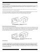
When the installation is completed, turn on the fan and make sure that there are no obstructions in the line.
Gas Line Installation
The Model 7200 / 9200 are set for natural gas (NG) OR propane (LP) gas at the factory. Be sure your range is
THE RANGE MUST BE INSTALLED IN COMPLIANCE WITH LOCAL CODES, AND IN THE ABSENCE OF LOCAL
REQUIREMENTS, THE INSTALLATION MUST COMPLY WITH REQUIREMENTS OF ANSI Z223.1/NFPA 54 IN UNITED
STATES AND C.S.A. B149.1 IN CANADA.
Note: Appliances installed in the state of Massachusetts:
- A “T” handle type manual gas valve must be installed in the gas supply line to this appliance.
THE APPLIANCE MUST BE ISOLATED FROM THE GAS SUPPLY PIPING SYSTEM BY CLOSING ITS INDIVIDUAL
MANUAL SHUTOFF VALVE DURING ANY PRESSURE TESTING OF THE GAS SUPPLY PIPING SYSTEM AT TEST
PRESSURES EQUAL TO OR LESS THAN 3.5 KPS (1/2 PSIG).
The maximum propane/natural gas supply inlet must not exceed 14 inches of water column. The minimum gas supply
inlet should be at least 5 inches of water column for natural gas or at least 11 inches of water column for LP gas.
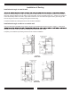
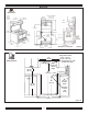
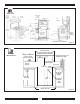
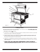
34”
86 cm
3-3/4” 10 cm
30”
76 cm
4-3/4”
12 cm
10” 25 cm
Gas Inlet to Manifold
Gas Inlet to Manifold
9200 Gas Inlet Locations
7200 Gas Inlet Locations
Figure 7
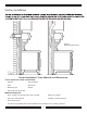
Installation must be done in accordance with all local and national codes. Use only materials which conform to local codes
in effect. Be sure power is disconnected before doing any electrical work. All duct work must be metal and mechanically
fastened. Do not use plastic duct. The range hood should never be exhausted into a wall cavity or an attic where an
accumulation of grease could become a fire hazard. Please ensure closet installation above the appliance conforms to
local code or in the absence of local code the National Fuel Gas Code ANSI Z233.1/NFPA 54.
.
.