HEAT CONTROLLER, INC. Through-The-Wall Air Conditioner MODELS: BDE-103-A BDE-123-A Service Manual CAUTION -Before servicing the unit, read the "safety precautions" in this manual. -Only for authorized service personnel.
CONTENTS 1. PREFACE 1.1 SAFETY PRECAUTIONS ...............................2 1.2 INSULATION RESISTANCE TEST.................2 1.3 FEATURES .....................................................4 1.4 CONTROL LOCATIONS .................................4 2.4 REFRIGERATION CYCLE............................10 2.4.1 CONDENSER ......................................10 2.4.2 EVAPORATOR ....................................10 2.4.3 CAPILLARY TUBE...............................10 2. DISASSEMBLY INSTRUCTIONS 3.
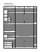
1.3 SPECIFICATIONS 1.3.1 FOR BDE-103-A/BDE-123-A MODELS ITEMS BDE-103-A CAPACITY 9,800/10,000 11,400/11,700 (W) 1,040/1,060 1,210/1,250 5.2/4.7 6.2/5.8 9.4 9.4 RUNNING CURRENT (A) (Btu/W.h) CAPACITY HEATING (Btu/h) INPUT E.E.R. (Btu/h) 9,200/11,200 (W) 2,900/3,500 INPUT 14.0/15.3 RUNNING CURRENT (A) INDOOR (°C) OPERATING COOLING OUTDOOR (°C) TEMPERAINDOOR (°C) TURE HEATING OUTDOOR (°C) REFRIGERANT (R-22) CHARGE(g) EVAPORATOR 26.7 (DB) 19.4 (WB) 35 (DB) 23.9 (WB) 21.1 (DB) 15.
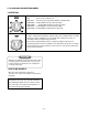
1.4 FEATURES • Designed for cooling only. • Side air-intake, side cooled-air discharge. • Powerful and quiet cooling. • Top-down chassis for the simple installation and service. • Built in adjustable THERMOSTAT. • Washable one-touch filter. • Compact size. 1.5 CONTROL LOCATIONS 1.5.1 COOLING ONLY MODEL • OPERATION Operation Off Med Fan High Cool Low Fan Med Cool Low Cool Off Med Fan Low Fan High Cool Med Cool Low Cool - Turns air conditioner off. - Med speed fan operation without cooling.
1.5.2 COOLING AND HEATING MODEL • OPERATION OFF - Turns the air conditioner off. FAN ONLY - The low fan speed operation without cooling/heating. LOW COOL - Cooling with the low speed fan operation. HIGH COOL - Cooling with the high speed fan operation. LOW HEAT - Heating with the low speed fan operation. HIGH HEAT - Heating with the high speed fan operation. Turn the Temperature Knob to the desired setting. The central position is a normal setting for average conditions.
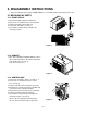
2. DISASSEMBLY INSTRUCTIONS — Before the following disassembly, POWER SWITCH is set to OFF and disconnected the power cord. 2.1 MECHANICAL PARTS 2.1.1 FRONT GRILLE 1. Open the inlet grille upward or downward. 2. Remove the screw which fastens the front grille. 3. Pull the front grille from the right side. 4. Remove the front grille. (See Fig. 1) 5. Re-install the component by referring to the removal procedure. Figure 1 2.1.2 CABINET 1.
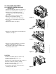
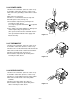
2.2 AIR HANDLING PARTS 2.2.1 ORIFICE, HEATER ASSY AND TURBO FAN 1. Remove the front grille. (Refer to section 2.1.1) 2. Remove the cabinet. (Refer to section 2.1.2) 3. Remove the 2 screws which fasten the evaporator at the left side and the right side. (See Fig. 4) 4. Move the evaporator sideward carefully. 5. Remove the 2 terminals carefully (See Fig. 5, at Electric Heater Model only) 6. Remove the 4 screws which fasten the orifice. (See Fig. 5) 7. Remove the orifice. (See Fig. 5) Figure 4 Figure 5 8.
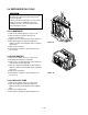
2.2.3 SHROUD 1. Remove the fan. (Refer to section 2.2.2) 2. Remove the screw which fasten the shroud. 3. Remove the shroud. (See Fig. 9) 4. Re-install the component by referring to the removal procedure, above. 2.3 ELECTRICAL PARTS 2.3.1 MOTOR 1. Remove the cabinet. (Refer to section 2.1.2) 2. Remove the clamp cord and disconnect a wire housing in control box. (Refer to section 2.1.3) 3. Remove the turbo fan. (Refer to section 2.2.2) 4. Remove the fan. (Refer to section 2.2.2) 5.
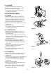
2.3.4 POWER CORD 1. Remove the control box. (Refer to section 2.1.3) 2. Unfold the control box. (Refer to section 2.3.3) 3. Disconnect the grounding screw from the control box. 4. Disconnect 2 receptacles. 5. Remove a screw which fastens the clip cord. 6. Pull the power cord. (See Fig. 13) 7. Re-install the component by referring to the removal procedure, above. (Use only one ground-marked hole for ground connection.) 8.
2.4 REFRIGERATION CYCLE CAUTION Discharge the refrigerant system using FreonTM Recovery System. If there is no valve to attach the recovery system, install one (such as a WATCO A-1) before venting the FreonTM. Leave the valve in place after servicing the system. 2.4.1 CONDENSER 1. Remove the cabinet. (Refer to section 2.1.2) 2. Remove the brace and the shroud cover. (Refer to section 2.2.1) 3. Remove the 5 screws which fasten the condenser. 4.
NOTES — Replacement of the refrigeration cycle. 1. When replacing the refrigeration cycle, be sure to discharge the refrigerant system using a FreonTM recovery System. If there is no valve to attach the recovery system, install one (such as a WATCO A-1) before venting the FreonTM. Leave the valve in place after servicing the system. 2. After discharging the unit completely, remove the desired component, and unbrace the pinch-off tubes. 3.
Equipment needed: Vacuum pump, Charging cylinder, Manifold gauge, Brazing equipment. Pinch-off tool capable of making a vapor-proof seal, Leak detector, Tubing cutter, Hand Tools to remove components, Service valve.
3. INSTALLATION Dimension of air conditioner 3.1 HOW TO INSTALL THE UNIT 24-21/32" (626 mm) CAUTION • There are sharp edges that can cause serious cuts. • When lifting the air conditioner, it is HEAVY. Use 2 peoples to lift. 14-13/32" (366 mm) For existing sleeve, you should measure the wall sleeve dimensions. You can install the new air conditioner according to these installation instructions to achieve the best performence.
3.
3.3 SUGGESTED TOOL REQUIREMENTS SCREWDRIVER(+, -), RULER, KNIFE, HAMMER, PENCIL, LEVEL 3.3.1 PREPARATION OF SLEEVE 1. Remove the old air conditioner from the wall sleeve and prepare the wall sleeve. Clean the interior of the sleeve (do not disturb the insulation or seals). The wall sleeve must be fastened in the wall securely before installing the new air conditioner. 2. Prepare the wall sleeve for installation of the new unit according to the following installation procedures.
Remove the backing from vertical and horizontal insulation and attach them to the inside of the wall sleeve as shown below. Remove the backing from the support blocks and attach them to the inside of the wall sleeve as shown below. Slide the baffles in the slots of the support blocks. A+1/4" (6 mm) B+1/4" (6 mm) Wall Insulation Horizontal Wall Sleeve Insulation Vertical Front 3.3.2 UNIT INSTALLATION A 1.
4. TROUBLESHOOTING GUIDE 4.1 OUTSIDE DIMENSIONS 24-21/32" (626mm) 14-13/32" (366mm) 19-21/32" (499mm) 4.2 PIPING SYSTEM CONDENSER COILS FAN CAPILLARY TUBE MOTOR COMPRESSOR TURBO FAN EVAPORATOR COILS : REFRIGERANT FLOW Following is a brief description of the important components and their functions in the refrigeration system. Refer to Fig. 19 to follow the refrigeration cycle and the flow of the refrigerant in the cooling cycle.
4.3 TROUBLESHOOTING GUIDE In general, possible trouble is classified in two causes. The one is called Starting Failure which is caused from an electrical defect, and the other is Ineffective Air Conditioning caused by a defect in the refrigeration circuit and improper application. Unit is running but cooling is ineffective Ineffective Cooling Check of cold air circulation for smooth flow. Check of outdoor coil (heat exchanger) & the fan operation. Dirty indoor coil (Heat exchanger) Check gas leakage.
Fails to Start Check of power source. Check of circuit breaker and fuse. Check of control switch setting. Gas leakage of feeler bulb of thermostat Check of control switch. Only compressor fails to start. Only fan fails to start. Improper wiring. Drop of power voltage. Improper thermostat setting Defect of fan motor capacitor. Defect of compressor capacitor. Loose terminal connection. Check capacitor. Irregular motor resistance ( ). Irregular motor insulation ( ). Improper wiring Replacement.
COMPLAINT Fan motor will not run. CAUSE REMEDY No power Check voltage at outlet. Correct if none. Power supply cord Check voltage to rotary switch. If none, check power supply cord. Replace cord if circuit is open. Rotary switch Check switch continuity. Refer to wiring diagram for terminal identification. Replace switch if defective. Wire disconnected or connection loose Connect wire. Refer to wiring diagram for terminal identification. Repair or replace loose terminal.
COMPLAINT Compressor will not run, but fan motor runs. CAUSE REMEDY Voltage Check voltage. See the limits on the preceding. page. If not within limits, call an electrician. Wiring Check the wire connections, if loose, repair or replace the terminal. If wires are off, refer to wiring diagram for identification, and replace. Check wire locations. If not per wiring diagram, correct. Rotary Check for continuity, refer to the wiring diagram for terminal identification.
COMPLAINT Compressor cycles on overload. Insufficient cooling or heating Excessive noise. REMEDY CAUSE Voltage Check the voltage. See the limits on the preceding page. If not within limits, call an electrician. Overload Check overload, if externally mounted. Replace if open. (If the compressor temperature is high, remove the overload, cool, and retest.) Fan motor If not running, determine the cause. Replace if required. Condenser air flow restriction Remove the cabinet.
5. SCHEMATIC DIAGRAM 5.1 CIRCUIT DIAGRAM • MODEL : BDE-103-A/BDE-123-A POWER INPUT BK(BR) (Plain) WH(BL) (Ribbed) ROTARY SWITCH GN/YL RD 8 7 2 1 6 L BL 4 H BK BL BK MOTOR 3 OR(BR) 2 1 CAPACITOR YL BL YL OR(BR) F THERMOSTAT H C WH C 5 BK RD RD L 4 R 7 COMP S C BR(YL) BK BK C RD RD H BL BL O.L.P RD RD FUSE LINK WIRING DIAGRAM NO.
6.
7. REPLACEMENT PARTS LIST R: Service Parts N: Non Service parts • MODEL: BDE-103-A/BDE-123-A A B C PART NO. LOCATION NO.
Specifications and performance data subject to change without notice. HEAT CONTROLLER, INC. 1900 WELLWORTH AVENUE • JACKSON, MICHIGAN 49203 THE QUALITY LEADER IN CONDITIONING AIR P/No.