HEAT CONTROLLER, INC. Dehumidifier MODELS: BHD-301-D BHD-501-D BHD-651-D Service Manual CAUTION -Before servicing the unit, read the "safety precautions" in this manual. -Only for authorized service personnel.
CONTENTS 1. PREFACE 1.1 SAFETY PRECAUTIONS ...........................................................................................................................3 1.2 FEATURES AND DIMENSIONS ................................................................................................................3 1.2.1 FEATURES........................................................................................................................................3 1.2.2 DIMENSIONS ................................
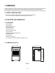
1. PREFACE This Service Manual provides various service information, including the mechanical and electrical parts. This dehumidifier was manufactured and assembled under the strict quality control procedures. The refrigerant is charged at the factory. Be sure to read the safety precaution prior to servicing the unit. 1.1 SAFETY PRECAUTIONS • Disconnect the power supply before servicing or replacing any component. • Do not cut off the grounding prong or alter the plug in any manner. 1.
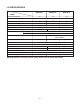
1.3 SPECIFICATIONS MODELS ITEMS CAPACITY(Pints/24hrs) BHD-301-D 30 BHD-501-D BHD-651-D 50 POWER SUPPLY(Phase,V,Hz) 65 1Ø, 115V,60Hz INPUT(W) 490 615 710 RUNNING CURRENT(A) 4.8 5.9 7.0 ENERGY FACTOR(L/kw.h) 1.2 1.6 1.80 REFRIGERANT R22 REFRIGERANT CHARGE, oz(g) THERMISTOR 5.29(150) 7.23(205) OPEN 33.8˚F(1±0.5°C) CLOSE 50˚F(10±0.5°C) SOLENOID VALVE 8.82(250) Using Temp/Humid.:-4~122˚F(-20~50°C)/95%RH Rating:7W/90mA COMPRESSOR MODEL No.
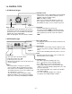
1.4 CONTROL TYPE 1.4.1 Mechanical type 4 5 3 6 7 2 Auto Shut-Off High 8 9 1 Off Max Low Fan Speed Humidity Control Humidity Control • When you first use the dehumidifier, turn the humidity control to 5 or 6. If you still have moisture, turn the humidity control to a higher setting. MAX is the highest setting. • When excess moisture and dampness odors are gone, adjust the control to a lower setting. Use the dehumidifier as long as excess moisture is present.
1.5 HOW TO OPERATE DEHUMIDIFIER 1.5.1 HOW DOES THE DEHUMIDIFIER WORK? Motor Condenser Fan Evaporator Moist, humid air is drawn over a cold refrigerated dehumidifying coil. Moisture in the air condenses on this coil and drains into a bucket (or through the bucket into a hose and drain). Dry, clean air is drawn over the condenser where it is actually heated several degrees and discharged out the rear grill into the room.
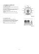
1.5.5 HUMIDITY CONTROLLER 42% R.H 1.5.5.1 Mechanical Type The humidity control can be set anywhere between Off and Max for normal operation. If you need more dehumidification, turn the Humidity Control toward Max. If you need less dehumidification, turn the Humidity Control toward Off. The relative humidity range is from 20% to 80%. (See Figure 6) Turn the Humidity Control to Off to stop the unit manually. 4(50%) 5(42%) 40% 3(60%) 6(35%) 7(30%) 2(70%) 8(25%) 9(20%) 1(80%) Off DEAD DIAL Max.
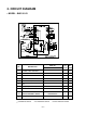
2. CIRCUIT DIAGRAM • MODEL : BHD-301-D PART NO. DESCRIPTION NO.
• MODEL : BHD-501-D/BHD-651-D WIRING DIA GRAM C WH(BL) (N) C BK GN/YL H R COMP. S C CAPACITOR BR RD BL RY-HI WH L F RY- O YL CN-DISP RD(LOW) OR(COM) CAPACITOR MOTOR GN/YL MAIN PCB CN-FAN CN-AC1 BUCKET CN-SEN S/W HUMIDITY SENSOR CN-AC2 POWER SMPS RY-COMP 4 3 FUSE 250V T3.15A O.L.P BK(BR) (L) THERMISTOR 3854A2024 0247Z PART NO. DESCRIPTION NO. DISPLAY P.C.
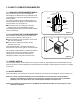
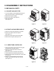
3. DISASSEMBLY INSTRUCTIONS 3.1 MECHANICAL PARTS 3.1.1 BUCKET AND AIR FILTER 1. Turn the Humidity Control off(Mechanical type) or press the power button off. (Electronic type) 2. Disconnect the power supply. 3. Remove the bucket. (See Figure 9) 4. Pull out the air filter. (See Figure 10) Figure 9 Figure 10 Figure 11 Figure 12 Figure 13 Figure 14 3.1.2 FRONT CASE AND REAR GRILLE 1. Remove 2 screws which fasten the front grille. 2. Pull the front grille forward and upward. (See Figure 11) 3.
3.2 CONTROL PARTS 3.2.1 POWER CORD ASSEMBLY 1. After opening the control box, remove the screw that holds the ground wire. (See Figure 15) 2. Disconnect the remaining leads of the power cord from the PWB(PCB) ASSEMBLY, MAIN, then remove it from the control box. Figure 15 3.2.2 SENSOR ASSEMBLY 1. Disconnect the sensor assembly from the PWB(PCB) ASSEMBLY, MAIN. 2. Remove the screw which fastens the humidity sensor. (See Figure 16) 3. Remove the thermistor from the holder. (See Figure 16) 4.
3.2.6 CONTROL PANEL 3.2.6.1 CONTROL PANEL - Mechanical Type (BHD-301-D) 1. Disconnect housing and all leads of the rocker switch, SWITCH ASSEMBLY, ROTARY and PWB(PCB) ASSEMBLY, DISPLAY from PWB(PCB) ASSEMBLY, MAIN (3.1.3) 2. Pull out the knob assembly. 3. Remove the nut which fastens the SWITCH ASSEMBLY, ROTARY. 4. Remove the knob of the rotary switch by pulling it upward. 5. Pull out the rocker switch by pushing the hooks on the both sides of rocker switch. 6.
3.2.7 FAN AND MOTOR 1. Turn the nut left and full out the Fan by hands carefully. 2. Remove 2 screws that fasten Heat Exchange. 3. Lift the H/E and open the H/E around 45 degree clockwise carefully. (See Figure 21) 4. Unfasten 3 screws that secure the Motor and earth wire. (See Figure 22) 5. Remove the Motor. Figure 21 Figure 22 3.2.8 SHROUD AND DRAIN PAN 1. Discharge the refrigerant by using a refrigerant Recovery System. 2.
3.3 REFRIGERATING CYCLE 3.3.1 CONDENSER, EVAPORATOR AND CAPILLARY TUBE 1. Remove the insulation on the Heater/Evaporator (H/E) assembly 2. Pierce the pinch-off tube to discharge the refrigerant, using a refrigerant recovery system. 3. After discharging the refrigerant completely, remove 2 screws between the housing assembly and the H/E. (See Figure 25) 4. Lift the H/E and open the H/E around 45 degree counterclockwise carefully. 5.
3.4 HOW TO REPLACE THE REFRIGERATION SYSTEM 1. When replacing a refrigeration component, be sure to discharge the refrigerant system by using a refrigerant recovery system. 2. After discharging the unit completely, remove the desired component, and unbraze the pinch-off tubes. 3. Solder service valves into the pinch-off tube ports, leaving the valves open. 4. Solder the pinch-off tubes with service valves. 5.
Equipment needed: Vacuum pump, charging cylinder, manifold gauge, brazing equipment. pinch-off tool capable of making a vapor-proof seal, leak detector, tubing cutter, hand tools to remove components, service valve.
4. TROUBLESHOOTING GUIDE CONDITION 1. Dehumidifier does not start. (Both compressor and fan motor do not operate.) CAUSE REMEDY No power Check power supply at outlet. Correct if none. Poor plug contact at outlet. Install plug properly or replace it. Bucket is full. If Auto Shut Off lights, empty the bucket and replace properly. Humidity control is at Off position Turn the humidity control switch toward Max. Wire disconnected or loose Connect wire.
CONDITION 5. Noisy operating 6. Water drips 7. Compressor cycles on overload protector. (OLP) CAUSE REMEDY Fan If cracked, out of balance, or partially missing, replace it Loose foreign material inside the housing. Remove it. Tube hits frame. Adjust tubing routine carefully. Fan blade hits frame Check Motor Mount. If loose, tighten it. Internal compressor noise. Replace compressor. Loose set screws Tighten them.
5.
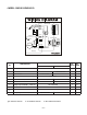
• MODEL:BHD-501-D W0CZZ-2 149980 349600 554030 354210 W0CZZ 359012 268711-2 249950 346811 435300 264110 131400 165010 135312 238310 235512 268711-1 436500 352113 35211A 152302 266010 552111 752140 330870 567502 130410 554160 148391 144410 550140 — — —20—
• MODEL:BHD-651-D W0CZZ-2 149980 349600 554030 W0CZZ 359012 354210 268711-2 249950 346811 435300 264110 131400 165010 135312 238310 235512 268711-1 436500 552111 35211A 152302 266010 352113 752140 330870 567502 130410 554160 148391 144410 550140 — — —21—
6. REPLACEMENT PARTS LIST • MODEL: BHD-301-D LOCATION No.
• MODEL: BHD-501-D LOCATION NO 130410 131400 135312 144410 148391 149980 152302 165010 235512 238310 249950 264110 266010 330870 346811 349600 352113 354210 359012 435300 436500 550140 552111 554030 554160 567502 752140 268711-1 268711-2 35211A W0CZZ W0CZZ-2 PART NO DESCRIPTION BHD-501-D Base Assembly,Single Cabinet Grille Assembly,Front Roller Tank Assembly,Bucket Shroud Filter,Air Sensor Assembly Cover Assembly,Display Escutcheon Case Assembly,Control Power Cord Assembly Switch Assembly Pan Assembly,D
• MODEL: BHD-651-D LOCATION No.
MEMO —25—
MEMO —26—
Specifications and performance data subject to change without notice. HEAT CONTROLLER, INC. 1900 WELLWORTH AVENUE • JACKSON, MICHIGAN 49203 THE QUALITY LEADER IN CONDITIONING AIR P/No.