Ceiling Cassette Type Single-Zone Air Conditioning DMC24CA-1 DMC36CA-1 Before servicing the unit, read the “safety precautions” in this manual. Only for authorized service personnel.
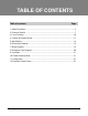
TABLE OF CONTENTS Table of contents Page 1. Safety Precautions ...........................................................................................................3 2. Feature & Benefits ...........................................................................................................7 3. List of Functions .............................................................................................................10 4. Function of Remote Control ............................................
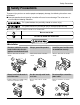
Safety Presautions Safety Precautions To prevent injury to the user or other people and property damage, the following instructions must be followed. ■ Incorrect operation due to ignoring instruction will cause harm or damage. The seriousness is classified by the following indications. This symbol indicates the possibility of death or serious injury. This symbol indicates the possibility of injury or damage to properties only. ■ Meanings of symbols used in this manual are as shown below.
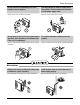
Safety Presautions Do not install, remove, or reinstall the unit by yourself (customer). • There is risk of fire, electric shock, explosion, or injury. Do not install the product on a defective installation stand. • It may cause injury, accident, or damage to the product. Be cautious when unpacking and installing the product. • Sharp edges could cause injury. Be especially careful of the case edges and the fins on the condenser and evaporator.
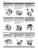
Safety Presautions Do not store or use flammable gas or combustibles near the product. • There is risk of fire or failure of product. If strange sounds, or small or smoke comes from product. Turn the breaker off or disconnect the power supply cable. • There is risk of electric shock or fire. nilosaG Do not open the inlet grill of the product during operation. (Do not touch the electrostatic filter, if the unit is so equipped.) • There is risk of physical injury, electric shock, or product failure.
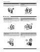
Safety Presautions Keep level even when installing the product. • To avoid vibration or water leakage. Use two or more people to lift and transport the product. • Avoid personal injury. 90˚ ■ Operational Use a soft cloth to clean. Do not use harsh detergents, solvents, etc. • There is risk of fire, electric shock, or damage to the plastic parts of the product. Do not touch the metal parts of the product when removing the air filter. They are very sharp! • There is risk of personal injury.
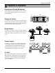
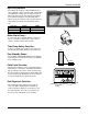
Features & Benefits Features & Benefits Environment Friendly Refrigerant : - LG Ceiling Cassette Air Conditioners uses environment friendly refrigerant, which don't do any harm to the environment. Dust electrode discharge Dust particles Pre-filter Plasma Air Purifier : - It removes not only microscopic contaminants & dust, but also house mites, pollen, and pet fur to help preventing allergic diseases like asthma.It provides odor free, dust free and allergy free air. Ionizer +6.
Features & Benefits Swirl Swing - It is the function for comfort cooling/heating operation. 4- Open(Conventional) Comparison of Floor Temp. Distribution(20°C) Swirl Swing(New) - The diagonal two louvers are opened the more larger than the other louvers. After one minute, it is opposite. 2.4% 100% Improved 4.
Features & Benefits High Ceiling Operation - According to the height of ceiling installation, it provides variability of indoor fan motor rpm. If the height of installation is low then you can adjust low rpm of indoor fan motor. On the other hand if the height of the installation is high you can adjust high rpm of indoor fan motor. Selection of speed can be done by slide switch at the back of the LCD wired remote. ex: Selection Lower Standard Higher Height 2.4m(7.9ft) 2.7m(8.9ft) 3.0m(9.
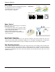
List of Functions List of Functions • Ceiling Cassette Category Air flow Air purifying Installation Reliability Convenience Individual Control CAC Network Function Special Function Kit Others Function Air supply outlet Airflow direction control (left & right) Airflow direction control (up & down) Auto swing (left & right) Auto swing (up & down) Airflow steps(Fan / Cool / Heat) CHAOS swing CHAOS wind (Auto wind) Jet cool (Power wind) Swirl wind Deodorizing filter Plasma air purifier Prefilter(Washa
Function of Remote Control Function of Remote Control 1. Wireless LCD Remote Control Signal transmitter 5 1 6 3 4 2 7 11 8 13 10 CANCEL ON OFF 9 12 17 SET AUTO CLEAN °C/°F 18 14 16 15 Flip-up door (opened) Operation Mode Cooling Operation Auto Operation Healthy Dehumidification Operation 1. START/STOP BUTTON Operation starts when this button is pressed and stops when the button is pressed again. 2. OPERATION MODE SELECTION BUTTON Used to select the operation mode. 3.
Function of Remote Control 2. Wired LCD Remote Control AUTO SWING OPERATION SET TEMP Room Temp 2ndF Timer FAN SPEED SUB FUNCTION HI MED LO AUTO Heater Preheat JET Defrost Humidify SLo Filter Out door ZONE 1 2 3 4 Time 1 Operation unit No Func Program set On Off Set no.
Specifications Specifications Indoor unit type Ceilling Cassette - 4way Model Power supply Phase/Volts/Hz Cooling capacity Heating capacity Current Nominal running current Fan Motor Type 1 / 208-230 / 60 1 / 208-230 / 60 kW 7.03 9.96 24,000 34,000 kW - - Btu/h - - A 1.0 1.0 BLDC BLDC Turbo Fan Turbo Fan 50.6 * 1 50.6 * 1 cmm 18.4/17.0/15.6 24.1/22.7/21.
Specifications Outdoor Unit Rated Capacity Cooling Heating Rated Input Cooling Heating kW Btu/h kW Btu/h kW kW Energy Label Testing combination Running current Cooling A Heating A Starting current (Cooling/Heating) A Power supply Phase / Volts / Hz Power supply Cable(outdoor) No. * mm2(No. AWG) Power and transmission cable No. * mm2(No.
Dimensional Drawings Dimensional Drawings 1. Indoor Units Model No.: DMC24CA-1 / DMC36CA-1 900(35.4) (ceiling opening) 840(33.1) 688(27.1) (hanging bolt) 950(37.4) 950(37.4) 840(33.1) 806(31.7) (hanging bolt) 950(37.4) 900(35.4) (ceiling opening) 225(8.9) 950(37.4) 840(33.1) 688(27.1) 1 950(37.4) 3 840(33.1) 806(31.7) 2 4) 1. 5( R3 6 840(33.1) 4 225(8.9) 76(3.0) 135(5.3) 30(1.18) 5 7 * mm(inch) No.
Dimensional Drawings 2. Outdoor Units Model No.: DMC24CA-1 870(34.3) 546(21.5) 54.6(2.1) 360(14.2) 10(0.4) 340(13.4) 320(12.6) 160(6.3) 320(12.6) 16 Ceiling Cassette Air Conditioner Ø5 31( 20. 9) 80(3.1) 50(2.0) 25.5(1.0) 392(15.4) 782.5(30.8) 808(31.8) 333(13.
Dimensional Drawings Model No.: DMC36CA-1 175(6.9) 15(0.6) 370(14.6) 395(15.6) 900(35.4) 550(21.7) 370(14.6) 520(20.5) 4 1135(44.7) 565(22.2) 1165(45.9) 1 3 80(3.1) 124(4.9) 273(10.7) 65(2.6) 2 5 308(12.1) *mm(inch) No.
Wiring Diagrams Wiring Diagrams 1.
Wiring Diagrams 2.
Refrigerant Cycle Diagrams Refrigerant Cycle Diagrams 1. Cooling Only Models INDOOR UNIT OUTDOOR UNIT High pressure S/W Thermistor Thermistor Gas Side H/EX Accumulator Thermistor (Air) Constant Compressor 2 Capillary Tube Check Valve Constant Compressor 1 Check Valve Heat Exchanger GAS SIDE Thermistor E.E.V. LIQUID SIDE Capacity 24k 34k Pipe Size(Diameter:Ø) inch Gas Liquid 1/4 1/4 1/2 5/8 20 Ceiling Cassette Air Conditioner Piping length (ft.) Elevation (ft.) Rated Max.
Installation Installation 1. Select the best location Install the air conditioner in the location that satisfies the following conditions. Above 250(98.4) 400(157.5) or less 50(19.7) or more 100(39.4) or more Ceiling Ceiling Board Ceiling Board 50(19.7) or more 30(11.8) or less • There should not be any heat source or steam near the unit. • There should not be any obstacle to the air circulation. • A place where air circulation in the room will be good.
Installation 2. Settlement of outdoor unit • Anchor the outdoor unit with a bolt and nut(ø10mm(0.39inch)) tightly and horizontally on a concrete or rigid mount. • When installing on the wall, roof or rooftop, anchor the mounting base securely with a nail or wire assuming the influence of wind and earthquake. Tubing connection Bolt • In the case when the vibration of the unit is conveyed to the hose, secure the unit with an anti-vibration rubber. 150mm(5.91inch) 3.
Installation 4. Wiring Connection 1. All wiring must comply with local and national electrical codes. 2. Select a power source that is capable of supplying the current as required by the air conditioner. 3. Feed the power source to the unit via a distribution switch board designed for this purpose. 4. The terminal screws inside the control box may be loose due to vibration during transport. Check the screws for loose connection.
Installation 5. Installation of Decoration Panel Before installing the decoration panel, always remove the paper template. The decoration panel has its installation direction. 1. Temporarily fix two decoration panel fixing screws (hexagon M5 screw) on the unit body. (Tighten by amount 10mm(0.39inch) in length.) The fixing screws (hexagon M5 screw) are included the indoor unit box. 2. Remove the air inlet grille from the decoration panel. (Remove the hook for the air inlet grille cord.) 3.
Installation 6. Heat Insulation and pipings HEAT INSULATION 1. Use the heat insulation material for the refrigerant piping which has an excellent heat-resistance (over 120°C(248°F) ). 2. Precautions in high humidity circumstance: This air conditioner has been tested according to the "KS Standard Conditions with Mist" and con here is not any default. However, if it is operated for a long time in high humid atmosphere (dew point temperature: more than 23°C(73.4°F)), water drops are liable to fall.
Installation Seal a small opening around the pipings with gum type sealer. In case of the Outdoor Unit being installed above position of the Indoor Unit. Trap 2. Tape the Piping and Connecting cable from bottom to top. 3. Form the pipings gathered by taping along the exterior wall, and make the trap prevent water from entering into the room. 4. Attach the piping onto the wall by saddle or equivalent. 7.
Installation 8. Test running 1) PRECAUTIONS IN TEST RUN • The initial power supply must provide at least 90% of the rated voltage. Otherwise, the air conditioner should not be operated. CAUTION For test run, carry out the cooling operation first even during winter season. Carry out the test run more than 5 minutes without stopping.
Installation 2) Connection of power supply 1. Connect the power supply cord to the independent power supply. • Circuit breaker is required. 2. Operate the unit for fifteen minutes or more. 3) Evaluation of the performance 1. Measure the temperature of the intake and discharge air. 2. Ensure the difference between the intake temperature and the discharge one is more than 8°C(14.4°F).
Installation 9. Optional Operation 1) Two Thermistor System (1) Open the rear cover of the wired remote-controller to set the mode. (2) Select one of three selectable modes as follows. • Position 1: The room themperature is controlled by the thermistor of the wired remote-controller, control the temperature according to the position of wired remote-controller. • Position 2: The room temperature is controlled by the thermistor of the main body.
Installation 2) Adjusting air volume to the height of ceiling You can choose the RPM(or air volume) of indoor motor according to the height of ceiling to supply the comfortable atmosphere to consumers. Procedure 1. Choose the selectable position in the table after measuring the height of ceiling. Ceiling height more than 3.3m(10.8ft) 2.7~3.3m(8.9~10.8ft) less than 2.7m(8.
Troubleshooting Guide Troubleshooting Guide Cycle Troubleshooting Guide Trouble analysis 1. Check temperature difference between intake and discharge air, and operating current. Temp. difference Current : approx. 0°C(0°F) : less than 80% of rated current All amount of refrigerant leaked out. Check refrigeration cycle. Temp. difference Current : approx. 8°C(14.4°F) : less than 80% of rated current Refrigerant leakage Clog of refrigeration cycle Defective compressor Temp.
Troubleshooting Guide Electronic Parts Troubleshooting Guide Trouble 1 The Product doesn’t operate at all. Turn off the main power and wait until LED on outdoor PCB is off Turn on the main power again. Does the Operating LED of indoor unit blink When Operation's ON? Refer to the self-diagnosis function.
Troubleshooting Guide Trouble 2 Product doesn't operate with the remote controller. Turn on main power. While the compressor has been stopped, the compressor does not operate owing to the delaying function for 3 minutes after stopped. When the compressor stopped Indoor Fan is driven by a low speed. At this point the wind speed is not controlled by the remote controller. (When operated in the Sleeping Mode, the wind speed is set to the low speed as force.) Caused by the remote controller.
Troubleshooting Guide Trouble 3 When cooling does not operate Turn on Main Power Operate "Cooling Mode( )" by setting the desired temperature of the remote controller to at least 1°C(1.8ºF) below room temperature. When in Air Circulation Mode, Compressor/Outdoor Fan is stopped. Check the sensor for indoor temperature is attached as close as to be effected by the temperature of Heat Exchanger(EVA).
Troubleshooting Guide Trouble 4 When indoor Fan does not operate Turn off Main power Check the connection of CN-FAN or CN-MOTOR Check the Fan Motor Check the Fuse(AC250V/T2A) Check the related circuit of indoor Fan Motor. • The pin of Micom, and the part for driving SSR • Check the pattern • Check the SSR - SSR Open: Indoor Fan Motor never operate - SSR short: Indoor Fan Motor always operates in case of ON or OFF. Turn ON Main Power Check the SSR high speed operation by remote control.
Troubleshooting Guide Trouble 5 When Vertical Louver does not operate • Confirm that the Vertical Louver is normally geared with the shaft of Stepping Motor. • If the regular torque is detected when rotating the Vertical Louver with Normal hands • Check the connecting condition of CN-U/D Connector • Check the soldering condition(on PWB) of CN-U/D Connector Check the operating circuit of the Vertical Louver • Confirm that there is DC +12V between pin GND.
Troubleshooting Guide Self-diagnosis Function ■ Error Indicator • The function is to self-diagnoisis airconditioner and express the troubles identifically if there is any trouble. • Error mark is ON/OFF for the operation LED of evaporator body in the same manner as the following table. • If more than two troubles occur simultaneously, primarily the highest trouble fo error code is expressed. • After error occurrence, if error is released, error LED is also released simultaneously.
Troubleshooting Guide Troubleshooting CH01, CH02, CH06 Display code Title 01 Indoor air sensor • Open / Short • Soldered poorly • Internal circuit error Normal resistor : 10KΩ/ at 25°C(77°F) (Unplugged) Normal voltage : 2.5Vdc / at 25°C(77°F) (plugged) 02 Indoor inlet pipe sensor • Open / Short • Soldered poorly • Internal circuit error Normal resistor : 5KΩ/ at 25°C(77°F) (Unplugged) Normal voltage : 2.
Troubleshooting Guide Troubleshooting CH03 Display code Title 03 Communication Wired R/C Cause of error Check point & Normal condition • Connection of wire • Main PCB Volt. DC12V • Noise interference • Open / Short • Wrong connection Wired R/C 12V S Indoor Unit GND 12V S GND 12Vdc 12Vdc V V Check the Volt. Check the Volt. Check Point 1. Check the wire connection. (Open / Short) → Repair the connection 2. Check the soldering state of connector.
Troubleshooting Guide Troubleshooting CH04 Display code Title 04 Drain pump / Float switch Cause of error • Float switch Open. (Normal : short) Check point & Normal condition • The connection of wire(Drain pump/ Float switch) • Drain pump power input. (220V) • Drain tube installation. • Indoor unit installation. (Inclination) CN Float 0Ω Ω Check the resistance Check Point 1. Check the wire connection. (Open, Soldered poorly) → Repair the connection or change the PCB. 2.
Troubleshooting Guide Troubleshooting CH05, CH53 Display code 05 / 53 Title Communication (Indoor → Outdoor) Cause of error • Communication poorly Check point & Normal condition • Power input AC 220V. (Outdoor, Indoor) • The connector for transmission is disconnected. • The connecting wires are misconnected. • The GND1,2 is not connected at main GND. • The communication line is shorted at GND. • Transmission circuit of outdoor PCB is abnormal. • Transmission circuit of indoor PCB is abnormal.
Troubleshooting Guide Troubleshooting CH24, CH25 Display code Title 24 Press S/W Open 25 Input voltage Cause of error Check point & Normal condition • Low / High press S/W open. • Check the connection of “CN_Press”. • Check the components. • Abnormal Input voltage (140Vac , 300Vac . • Check the power source. • Check the components. Check Point • CH 24 • CH 25 1. Check the connection of “CN_PRESS” 1. Check the power source. 2. Check the install condition for over load. 2.
Troubleshooting Guide Troubleshooting CH32, CH33 Display code Title 32 D-pipe (Inverter) temp. high (105°C(221°F) ) • Discharge sensor (Inverter) temp. high • Check the discharge pipe sensor for INV. • Check the install condition for over load. • Check the leakage of refrigerant. • Check the SVC V/V open. 33 D-pipe (Constant) temp. high (105°C(221°F) ) • Discharge sensor (Cons.) temp. high • Check the discharge pipe sensor for Cons. • Check the install condition for over load.
Troubleshooting Guide Troubleshooting CH41, CH44, CH45, CH46, CH47, CH65 Display code Title 41 D-pipe sensor (Inverter) • Open / Short • Soldered poorly • Internal circuit error • Normal resistor : 200KΩ / at 25°C(77°F) (Unplugged) • Normal voltage : 4.5Vdc / at 25°C(77°F) (plugged) 44 Air sensor • Open / Short • Soldered poorly • Internal circuit error • Normal resistor : 10KΩ / at 25°C(77°F) (Unplugged) • Normal voltage : 2.
Troubleshooting Guide Troubleshooting CH51, CH60 Display code 51 Title Capacity Error 60 EEPROM Check sum Cause of error • Over Capacity Combination • Undder Capacity Combination Check point & Normal condition • Check the indoor unit capacity. • Check the combination table. • Check the PCB ASM P/No. • Check the poor soldering. • Check sum error Check Point • CH 51 • CH 60 1. Check the indoor unit capacity. 1. Check the insertion condition of EEPROM. 2.
Troubleshooting Guide Troubleshooting CH61, CH62 Display code Title Cause of error 61 Condenser pipe sensor temp. high • Condenser pipe sensor detected high temp.(65°C)(149°F) • Check the load condition. • Check the sensor of Condenser pipe sensor. 62 Heat sink sensor temp. high • Heat sink sensor detected high temp.(85°C)(185°F) • Check the fan is locked. • Check the sensor of heat sink. Check point & Normal condition Heat Sink temp.
(3-way) Valve (3-way) Valve 3-way Valve (Liguid Side) 3-way Valve (Gas Side) Valve cap Valve cap Open position Closed position Open position Closed position Pin Pin To piping connection Service Service port cap port To outdoor unit 1.
(3-way) Valve (1) Pumping down Liquid side Indoor unit 3-Way valve Open Outdoor unit Gas side Closed 3-Way valve Lo CLOSE CLOSE Purge the air • Procedure For pumping down,firstly short the Low Pressure s/w at the outside and then operate below procedure. 1. Confirm that both the gas side and liquid side valves are set to the open position. - Remove the valve stem caps and confirm that the valve stems are in the raised position. - Be sure to use a hexagonal wrench to operate the valve stems. 2.
(3-way) Valve (2) Evacuation (All amount of refrigerant leaked) Liquid side Indoor unit Outdoor unit 2-Way valve Open Gas side 3-Way valve Open Vacuum pump Lo OPEN CLOSE • Procedure 1. Confirm that both the liguid side valve and gas side valve are set to the opened position. 2. Connect the vaccum pump to the center hose of the manifold gauge. 3. Connect the service port of the gas side valve to the low side of the gauge. 4. Evacuation for approximately one hour.
(3-way) Valve (3) Gas Charging (After Evacuation) Liquid side Indoor unit 2-Way valve Open Outdoor unit Gas side Open 3-Way valve Check valve Charging cylinder Lo (1) OPEN CLOSE • Procedure 1. Connect the gauge to the charging cylinder. - Connect the charge hose which you disconnected from the vacuum pump to the valve at the bottom of the cylinder. - If you are using a gas cylinder, also use a scale and reverse the cylinder so that the system can be charged with liquid. 2.
Electronic Control Device Electronic Control Device • Main P.C.
Specifications and performance data subject to change without notice.