HEAT CONTROLLER, INC. Wall Mounted Multi-Split System Air Conditioning/Heat Pump DMC24DB-1 DMH24DB-1 Before servicing the unit, read the “safety precautions” in this manual. Only for authorized service personnel.
Multi type Air Conditioner Service Manual TABLE OF CONTENTS Combination table.......................................................................................................................................3 Safety Precautions......................................................................................................................................4 Dimensions.....................................................................................................................................
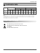
Combination table Combination table Heating Cooling Operation Combination of Indoor Unit(kBtu/h) Each Capacity Unit-A 1 Unit 12 2 Unit 12 Unit-B 12 Total UNIT-A(Btu/h) UNIT-B(Btu/h) Total Capacity Btu/h kW Each Capacity Total Capacity UNIT-A(Btu/h) UNIT-B(Btu/h) Btu/h kW 12 12000 - 12000 3516 12000 - 12000 3516 24 12000 12000 24000 7033 12000 12000 24000 7033 Notes : 1.Cooling Capacity is based on : indoor temp. 26.7°C(80.1°F)DB, 19.4°C(66.9°F)WB; outdoor temp.
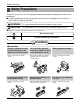
Safety Precautions Safety Precautions To prevent injury to the user or other people and property damage, the following instructions must be followed. ■ Incorrect operation due to ignoring instruction will cause harm or damage. The seriousness is classified by the following indications. WARNING This symbol indicates the possibility of death or serious injury. CAUTION This symbol indicates the possibility of injury or damage to properties only.
Safety Precautions Do not install, remove, or reinstall the unit by yourself (customer). • There is risk of fire, electric shock, explosion, or injury. Do not install the product on a defective installation stand. • It may cause injury, accident, or damage to the product. Do not allow water to run into electric parts. • It may cause There is risk of fire, failure of the product, or electric shock. Be cautious when unpacking and installing the product. • Sharp edges could cause injury.
Safety Precautions When flammable gas leaks, turn off the gas and open a window for ventilation before turn the product on. • Do not use the telephone or turn switches on or off. There is risk of explosion or fire Do not open the inlet grill of the product during operation. (Do not touch the electrostatic filter, if the unit is so equipped.) • There is risk of physical injury, electric shock, or product failure. If strange sounds, or smoke comes from product. Turn the breaker off.
Safety Precautions When the product is not to be used for a long time, disconnect the power by turning off the breaker. Take care to ensure that nobody could step on or fall onto the outdoor unit. • There is risk of product damage or failure, or unintend- • This could result in personal injury and product damed operation. age. CAUTION ■ Installation Always check for gas (refrigerant) leakage after installation or repair of product. • Low refrigerant levels may cause failure of product.
Safety Precautions ■ Operational Do not expose the skin directly to cool air for long periods of time. (Don't sit in the draft.) • This could harm to your health. Use a soft cloth to clean. Do not use harsh detergents, solvents, etc. • There is risk of fire, electric shock, or damage to the plastic parts of the product. Do not use the product for special purposes, such as preserving foods, works of art, etc. It is a consumer air conditioner, not a precision refrigeration system.
Safety Precautions Use a firm stool or ladder when cleaning or maintaining the product. • Be careful and avoid personal injury. Do not recharge or disassemble the batteries. Do not dispose of batteries in a fire. • They may burn or explode. Replace the all batteries in the remote control with new ones of the same type. Do not mix old and new batteries or different types of batteries.
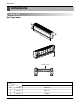
Dimensions Dimensions Indoor Unit Split Type Indoor H D W Installation plate Model Split Type(SE) 12 kBtu/h Dimension W mm(in) 895(35.2) H mm(in) 282(11.1) D mm(in) 165(6.
Dimensions Outdoor Unit L4 L1 H L3 L2 D W L6 L5 MODEL DIM L7 UE1 24kBtu/h W mm(in) 870(34.3) H mm(in) 800(31.5) D mm(in) 320(12.6) L1 mm(in) 370(14.6) L2 mm(in) 25(1.0) L3 mm(in) 775(30.5) L4 mm(in) 25(1.0) L5 mm(in) 546(21.5) L6 mm(in) 160(6.3) L7 mm(in) 160(6.
Product Specifications Product Specifications DMC24DB-1 Operation Cooling Capacity Moisture Removal ℓ/h(ft /h) Power Source ø, V, Hz Air Circulation m /min(ft3/min) Input Cooling 23,600/24,000 11,800/12,000 - - 2.4(0.085) 1.2(0.042) Btu/h Heating Capacity Noise Level ( Hi / Med / Low ) 1-Unit On 2-Unit On Unit Item 3 3 dB(A) Indoor – Outdoor Indoor W 9.4(331.9) – 36/32/29 54 2,390/2,390 1,420/1,420 - - 10.1/10.1 6.3/6.3 - - Runnig Cooling Current Heating E.E.R.
Product Specifications DMH24DB-1 Operation Cooling Capacity Btu/h Heating Capacity Moisture Removal ℓ/h(ft /h) Power Source ø, V, Hz Air Circulation m /min(ft3/min) Noise Level ( Hi / Med / Low ) Input Cooling 1-Unit On 2-Unit On Unit Item 23,600/24,000 11,800/12,000 23,600/24,000 11,800/12,000 2.4(0.085) 1.2(0.042) 3 3 dB(A) Indoor – Outdoor Indoor W 9.4(331.9) – 36/32/29 2,390/2,390 1,420/1,420 2,440/2,440 1,620/1,620 10.1/10.1 6.3/6.3 9.8/9.8 7.2/7.
Installation Installation Read carefully, and then follow step by step.
Installation Select the best location Indoor unit 1. Do not have any heat or steam near the unit. 2. Select a place where there are no obstacles in front of the unit. More than 5cm (2.0 inch) More than 5cm (2.0 inch) 3. Make sure that condensation drainage can be conveniently routed away. 4. Do not install near a doorway. More than 2.3m (90.6 inch) 5. Ensure the spaces indicated by arrows from the wall, ceiling, fence or other obstacles. More than 5cm (2.0 inch) 6.
Installation Piping length and elevation Multi Piping Type Capacity(Btu/h) 24k Max Elevation Max total length of Max length of each Min length of each between each all pipes (A+B) pipe (A/B) pipe (A/B) indoor unit and outdoor unit (h1) 30m(100ft) 15m(50ft) 3m(10ft) 7.5m(25ft) Max elevation between indoor units (h2) 7.5m(25ft) Pipe Size Indoor Capacity (Btu/h) Gas Liquid 12K 3/8" 1/4" 24k Standard Length 7.5m(25ft) Additional Refrigerant 20g/m(0.
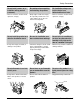
Installation Fixing Installation Plate(Standard Type) The wall you select should be strong and solid enough to prevent vibration 1. Mount the installation plate on the wall with type "A" screws. If mounting the unit on a concrete wall, use anchor bolts. • Mount the installation plate horizontally by aligning the centerline using a level. Installation Plate Chassis Hook Type "A" screw 2. Measure the wall and mark the centerline.
Flaring Work and Connection of Piping Flaring Work and Connection of Piping Flaring work Main cause for gas leakage is due to defect in flaring work. Carry out correct flaring work in the following procedure. Cut the pipes and the cable. 1. Use the piping kit accessory or the pipes purchased locally. 2. Measure the distance between the indoor and the outdoor unit. Copper pipe Slanted Uneven Rough 90° 3. Cut the pipes a little longer than measured distance. 4. Cut the cable 1.5m (5.
Flaring Work and Connection of Piping Check 1. Compare the flared work with the figure by. Smooth all round Inside is shiny without scratches 2. If a flared section is defective, cut it off and do flaring work again. = Improper flaring = Even length all round Inclined Surface Cracked Uneven damaged thickness Connecting the Piping Indoor 1. Prepare the indoor unit's piping and drain hose for installation through the wall. 2.
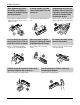
Flaring Work and Connection of Piping 4. Indoor unit installation Hook the indoor unit onto the upper portion of the installation plate.(Engage the two hooks of the rear top of the indoor unit with the upper edge of the installation plate.) Ensure that the hooks are properly seated on the installation plate by moving it left and right. Connecting cable Drain hose Press the lower left and right sides of the unit against the installation plate until the hooks engage into their slots(clicking sound).
Flaring Work and Connection of Piping For left rear piping 1. Route the indoor tubing and the drain hose to the required piping hole position. 1 2 2. Insert the piping, drain hose, and the connecting cable into the piping hole. Connecting cable 3. Insert the connecting cable into the indoor unit. • Don't connect the cable to the indoor unit. • Make a small loop with the cable for easy connection later. Drain pipe 4. Tape the drain hose and the connecting cables. 5.
Flaring Work and Connection of Piping Wrap the insulation material around the connecting portion. 1. Overlap the connection pipe heat insulation and the indoor unit pipe heat insulation material. Bind them together with vinyl tape so that there may be no gap. Plastic bands Insulation material 2. Wrap the area which accommodates the rear piping housing section with vinyl tape. Indoor unit piping Connection pipe Vinyl tape (wide) Wrap with vinyl tape Pipe Vinyl tape(narrow) Connecting cable 3.
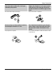
Flaring Work and Connection of Piping REMOTE CONTROL PREPARATION(OPTIONAL) HOW TO MOUNT ONTO A WALL HOW TO INSERT BATTERIES Remove the battery cover from the remote controller. • Slide the cover according to the arrow direction. Insert the two batteries. • Be sure that the (+) and (-) directions are correct. • Be sure that both batteries are new. Re-attach the cover. • Slide it back into position.
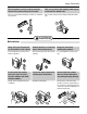
Flaring Work and Connection of Piping Outdoor Align the center of the pipings and sufficiently tighten the flare nut by hand. Finally, tighten the flare nut with torque wrench until the wrench clicks. Outdoor unit • When tightening the flare nut with torque wrench, ensure the direction for tightening follows the arrow on the wrench. Outside diameter mm inch Ø6.35 1/4 Ø9.52 3/8 Torque kg.m 1.8 4.2 lbf.in 156.2 364.
Flaring Work and Connection of Piping Connecting the Cable between Indoor Unit and Outdoor Unit Connect the cable to the Indoor unit. Connect the cable to the indoor unit by connecting the wires to the terminals on the control board individually according to the outdoor unit connection. (Ensure that the color of the wires of the outdoor unit and the terminal No. are the same as those of the indoor unit.) The earth wire should be longer than the common wires.
Connecting the Cable between Indoor Unit and Outdoor Unit Connect the cable to the Outdoor unit. 1. Remove the cover control from the unit by loosening the screw. Connect the wires to the terminals on the control board individually as the following. 2. Secure the cable onto the control board with the holder (clamper). 3. Refix the cover control to the original position with the screw.
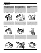
Connecting the Cable between Indoor Unit and Outdoor Unit Connection method of the connecting cable(Example) (1) Remove two-caps on the conduit panel. (2) Make a hole appropriate for the passage of connection cable through on cap by tool. (for low voltage line) (3) Pass the connecting cable through the hole. (4) Properly connect the cable on the terminal block.
Connecting the Cable between Indoor Unit and Outdoor Unit CAUTION: Provide a circuit breaker between power source and the unit as shown below. Main power source Air Conditioner Circuit Breaker Use a circuit breaker or time delay fuse. Model Power source Fuse or breaker Capacity 24k 1Ø, 230/208V Per max. fuse size on unit name plate Connect the cable to the indoor unit 1. Connect the wires to the terminals on the control board individually according to the outdoor unit connection.
Checking the Drainage, Forming the Pipings and Long Pipe Setting Checking the Drainage, Forming the Pipings and Long Pipe Setting Checking the drainage To check the drainage. 1. Pour a glass of water on the evaporator. 2. Ensure the water flows through the drain hose of the indoor unit without any leakage and goes out the drain exit. Drain piping 1. The drain hose should point downward for easy drain flow. Downward slope 2. Do not make drain piping.
Checking the Drainage, Forming the Pipings and Long Pipe Setting Forming the piping Form the piping by wrapping the connecting portion of the indoor unit with insulation material and secure it with two kinds of vinyl tape. Seal a small opening around the pipings with gum type sealer. Taping • If you want to connect an additional drain hose, the end of the drain outlet should be routed above the ground. Secure the drain hose appropriately.
Air Purging and Evacuation Air Purging and Evacuation Air and moisture remaining in the refrigerant system have undesirable effects as indicated below. 1. Pressure in the system rises. 2. Operating current rises. 3. Cooling(or heating) efficiency drops. 4. Moisture in the refrigerant circuit may freeze and block capillary tubing. 5. Water may lead to corrosion of parts in the refrigeration system.
Checking the Drainage, Forming the Pipings and Long Pipe Setting Evacuation 1. Connect the charge hose end described in the preceding steps to the vacuum pump to evacuate the tubing and indoor unit. Confirm the "Lo" knob of the manifold valve is open. Then, run the vacuum pump. The operation time for evacuation varies with tubing length and capacity of the pump. The following table shows the time required for evacuation.
Charging Charging ■ Each outdoor unit is factory charged (nameplate charge) for the evaporator as well as a 7.5m(25ft) line set for each indoor line. Any time total line set is used either shorter or longer then the nominal 22.5m(75ft: for tri-zone) line set length the refrigerant charge has to be adjusted. ■ Whether the line set is made shorter or longer you must adjust the charge based on how many ft of tubing are either added or removed based on 20g(0.22oz) of R-410A per meter(foot).
Test Running Test Running Split Type 1. Check that all tubing and wiring have been properly connected. 2. Check that the gas and liquid side service valves are fully open. 1) Prepare remote controller Remove the battery cover by pulling it according to the arrow direction. Insert new batteries making sure that the (+) and (–) of battery are installed correctly. Reattach the cover by pushing it back into position.
Operation Operation Function of control 1. MAIN UNIT FUNCTION • DISPLAY Operation Indicator • On while in appliance operation, off while in appliance pause • Flashing while in disconnection or short in Thermistor (3 sec off / 0.