HEAT CONTROLLER, INC. Wall Mounted Mini-Split System Single-Zone Air Conditioning/Heat Pump Service Manual DMC09SB-0/DMH09SB-0 DMC12SB-0/DMH12SB-0 DMC18SB-1/DMH18SB-1 DMC24SB-1/DMH24SB-1 Before servicing the unit, read the “safety precautions” in this manual. Only for authorized service personnel.
Air Conditioner Service Manual TABLE OF CONTENTS Safety Precautions..........................................................................................................................................3 Dimensions......................................................................................................................................................9 Symbols Used in this Manual ..................................................................................................................
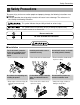
Safety Precautions Safety Precautions To prevent injury to the user or other people and property damage, the following instructions must be followed. ■ Incorrect operation due to ignoring instruction will cause harm or damage. The seriousness is classified by the following indications. This symbol indicates the possibility of death or serious injury. This symbol indicates the possibility of injury or damage to properties only. ■ Meanings of symbols used in this manual are as shown below.
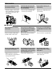
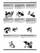
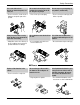
Safety Precautions Be sure the installation area does not deteriorate with age. Install the indoor unit on the wall where the height from the floors more than 8ft(2.4m) Do not handle the pipe by yourself(Costomer) • If the base collapses, the air conditioner could fall with it, causing property damage, product failure, and personal injury. • There are sharp moving parts that could cause personal injury. • High-Pressure refrigent may cause personal injury. 8ft(2.
Safety Precautions Stop operation and close any window in storm or hurricane before the hurricane arrives. Do not open the inlet grill of the product during operation. (Do not touch the electrostatic filter, if the unit is so equipped.) When the product is soaked (flooded or submerged), contact an Authorized Service Center. • There is risk of property damage, failure of product, or electric shock. • There is risk of physical injury, electric shock, or product. • There is risk of electrical shock.
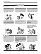
Safety Precautions ■ Installation Always check for gas(refrigerant) leakage after installation or repair of product. Install the drain hose to ensure that water is drained away properly. Keep level even when installing the product. • Low refrigerant levels may cause product failure. • A bad connection may cause water leakage. • To avoid vibration or water leakage. 90˚ Do not install the product where the noise or hot air from the outdoor unit could offend neighbors.
Safety Precautions Use a soft cloth to clean. Do not use harsh detergents, solvents, etc. Do not touch the metal parts of the product when removing the air filter. They are very sharp! Do not step on or put anything on the product. (outdoor unit) • There is risk of fire, electric shock or damage to the plastic parts of the product. • There is risk of personal injury. • There is risk of personal injury and failure of product. Always insert the filter securely.
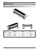
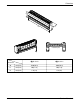
Dimensions Dimensions Indoor Unit H D W Installation plate Model Dimension 9 Btu Series (C/O) 9 Btu Series (H/P) 12 Btu Series W mm(inch) 840(33.1) 894(35.2) 894(35.2) H mm(inch) 270(10.6) 295(11.6) 295(11.6) D mm(inch) 153(6.0) 165(6.5) 165(6.
Dimensions H W D Installation plate Model Dimension 18 Btu Series 24 Btu Series W mm(inch) 1090(42.9) 1090(42.9) H mm(inch) 300(11.8) 300(11.8) D mm(inch) 178(7.0) 178(7.
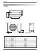
Dimensions Outdoor Unit 1. 9k, 12k L2 D L1 W H L3 L5 Gas side (3-way valve) L4 Liquid side (2-way valve) DIM MODEL unit 9k, 12k W mm(inch) 770(30.3) H mm(inch) 540(21.3) D mm(inch) 245(9.6) L1 mm(inch) 287(11.3) L2 mm(inch) 64(2.5) L3 mm(inch) 518(20.4) L4 mm(inch) 10(0.4) L5 mm(inch) 100(3.
Dimensions 2. 18k, 24k L4 L1 L10 L9 H L3 L2 D W L6 L5 MODEL DIM L7 L8 18k, 24k W mm(inch) 870(34.3) H mm(inch) 655(25.8) D mm(inch) 320(12.6) L1 mm(inch) 370(14.6) L2 mm(inch) 25(1.0) L3 mm(inch) 630(24.8) L4 mm(inch) 25(1.0) L5 mm(inch) 546(21.5) L6 mm(inch) 162(6.4) L7 mm(inch) 162(6.4) L8 mm(inch) 54(2.1) L9 mm(inch) 74.5(2.9) L10 mm(inch) 79(3.
Introduction Introduction Symbols Used In This Manual This symbol alerts you to the risk of electric shock. This symbol alerts you to hazards that may cause harm to the air conditioner. NOTICE This symbol indicates special notes.
Introduction Installation Read carefully, and then follow step by step.
Installation Installation Map NOTICE Installation parts you should purchase. Installation plate Sleeve Bushing-Sleeve Putty(Gum Type Sealer) Bend the pipe as closely on the wall as possible, but be careful that it doesn't break.
Installation Confirm The Refrigerant 1. Check the quality label on the indoor and outdoor unit. 2. Make certain that the refrigerant is R-410A. NOTICE THIS PRODUCT CONTAINS R-410A REFRIGERANT 1) Different compressor oil - R-410A(Polyol ester) / R-22(Mineral). - Do not mix the existing mineral oil. - Do not apply used pipe, tools and gauges covered with the existing mineral oil. 2) Absorption of moisture -Compressor’s oil has the high absorption rate of moisture.
Installation Select The Best Location Indoor unit 1. Do not have any heat or steam near the unit. 6. Use a stud finder to locate studs to prevent unnecessary damage to the wall. 2. Select a place where there are no obstacles in front of the unit. 3. Make sure that condensation drainage can be conveniently routed away. More than 30cm(11.8in) More than 12cm(4.7in) 4. Do not install near a doorway. 5. Ensure that the space around the left and right of the unit is more than 30cm(11.8in).
Installation Piping Length And Elevation Capacity (Btu/h) 9k Evap Standard Length m(ft) Max. Elevation B m(ft) Max. length A m(ft) Additional Refrigerant g/m(oz/ft) 1/4" 7.5(25) 7.5(25) 15(49) 20(0.22) Pipe Size Suction 3/8" 1/2" 1/4" 7.5(25) 7.5(25) 15(49) 20(0.22) 12k 1/2" 1/4" 7.5(25) 7.5(25) 15(49) 20(0.22) 18k 1/2" 1/4" 7.5(25) 15(49) 30(98) 20(0.22) 5/8" 1/4" 7.5(25) 7.5(25) 15(49) 20(0.22) 5/8" 1/4" 7.5(25) 7.5(25) 15(49) 20(0.
Installation How To Mount Installation Plate The wall you select should be strong and solid enough to prevent vibration 1. Mount the installation plate on the wall with type "A" screws. If mounting the unit on a concrete wall, use anchor bolts. • Mount the installation plate horizontally by aligning the centerline using a level. Installation Plate Chassis Hook Type “A” 2. Measure the wall and mark the centerline.
Installation Flaring Work Main cause for gas leakage is due to defect in flaring work. Carry out correct flaring work in the following procedure. Cut the pipes and the cable. 1. Use the piping kit accessory or the pipes purchased locally. 2. Measure the distance between the indoor and the outdoor unit. 3. Cut the pipes a little longer than measured distance. 4. Cut the cable 1.5m(59.1in) longer than the pipe length. Copper pipe Slanted Uneven Rough 90° Burrs removal Pipe 1.
Installation Connecting The Piping Indoor 1. Prepare the indoor unit's piping and drain hose for installation through the wall. 2. Remove the plastic tubing retainer(see the illustration by) and pull the tubing and drain hose away from chassis. 3. Replace only the plastic tubing holder 1, not the holder 2 in the original position. For left rear piping Route the indoor tubing and the drain hose in the direction of rear left.
Installation Connecting the pipings to the indoor unit and drain hose to drain pipe. • Put a couple drops of refrigerant oil on the face of the flare before assembling taking care not to add any contaminants. • Align the center of the pipings and sufficiently tighten the flare nut by hand. Indoor unit tubing Flare nut • Overlap the connection pipe insulation material and the indoor unit pipe insulation material. Bind them together with vinyl tape so that there is no gap.
Installation Insert the connecting cable into the indoor unit. Spanner (fixed) • Don't connect the cable to the indoor unit. Flare nut • Make a small loop with the cable for easy connection later. Tape the drain hose and the connecting cable. Connection pipe Torque wrench Indoor unit tubing Outside diameter mm inch • Connecting cable Tape Connecting pipe Drain hose Ø6.35 Ø9.52 Ø12.7 Ø15.88 Torque (lbf.ft) 13.0 30.4 39.8 47.7 1/4 3/8 1/2 5/8 • Mount the clamp on the boss with a type "B" screw.
Installation • Wrap the area which accommodates the rear piping housing section with vinyl tape. Indoor unit piping Connection pipe Vinyl tape (wide) Reroute the pipings and the drain hose across the back of the chassis. Wrap with vinyl tape Pipe Vinyl tape(narrow) Piping for passage through piping hole Connecting cable Reroute the pipings and the drain hose across the back of the chassis.
Installation Installation Information. For left piping. Follow the instruction below. Correct case • Press on the upper side of clamp and unfold the tubing to downward slowly. Incorrect case • Following bending type from right to left may cause damage to the tubing.
Installation Connection Of The Drain Hose • The drain hose can be connected at two different positions. Use the most convenient position and, if necessary, exchange the position of the drain pan, rubber cap and the drain hose. ➊ Drain pan ➋ Rubber cap ➌ Drain hose ➍ Exchange if necessary • Remove the drain hose. • Securely insert both the rubber plug and drain hose into the drain outlets. Be sure the rubber the cap is securely fastened so that there is no leakage.
Installation Connection Of The Cable 1. Remove the cover control from the unit by loosening the 3 screws. 2. Dismount caps on the conduit panel. 3. Temporarily mount the conduit tubes on the conduit panel. 4. Properly connect both the power supply and low voltage lines to the corresponding terminals on the terminal block. 5. Ground the unit in accordance with local codes. 6. Be sure to size each wire allowing several inches longer than the required length for wiring. 7.
Installation After the confirmation of the above conditions, prepare the wiring as follows: 1) Never fail to have an individual power circuit specifically for the air conditioner. As for the method of wiring, be guided by the circuit diagram posted on the inside of control cover. 2) The screw which fasten the wiring in the casing of electrical fittings are liable to come loose from vibrations to which the unit is subjected during the course of transportation.
Installation Checking The Drainage • Pour a glass of water on the drain pan. • Ensure the water flows through the drain hose of the indoor unit without any leakage and goes out the drain exit. Connecting area drain hose Leakage checking Drain pan Drain hose Leakage checking Drain piping • The drain hose should point downward for easy drain flow. Downward slope • Avoid these situations.
Installation Forming The Piping Form the piping by wrapping the connecting portion of the indoor unit with insulation material and secure it with two kinds of vinyl tapes. • If you want to connect an additional drain hose, the end of the drain outlet should be routed above the ground. Secure the drain hose appropriately. In cases where the outdoor unit is installed below the indoor unit perform the following. • Tape the piping, drain hose and connecting cable from down to up.
Installation Air Purging Air and moisture remaining in the refrigerant system have undesirable effects as indicated below. • Pressure in the system rises. • Operating current rises. • Cooling(or heating) efficiency drops. • Moisture in the refrigerant circuit may freeze and block capillary tubing. • Water may lead to corrosion of parts in the refrigeration system.
Installation Soap water method (1) Remove the caps from the gas side and liquid side valves. (2) Remove the service-port cap from the gas side valve. (3) To open the gas side valve turn the valve stem counterclockwise approximately 90°, wait for about 2~3 seconds, and close it. (4) Apply a soap water or a liquid neutral detergent on the indoor unit connection or outdoor unit connections by a soft brush to check for leakage of the connecting points of the piping.
Installation Charging ■ Each outdoor unit is factory charged (nameplate charge) for the evaporator as well as a 7.5m(25ft) line set. Any time a line set is used either shorter or longer then the nominal 7.5m(25ft) line set length the refrigerant charge has to be adjusted. ■ Whether the line set is made shorter or longer you must adjust the charge based on how many ft of tubing are either added or removed based on 20g(0.22oz) of R-410A per meter(foot). Capacity (Btu/h) 9k Evap Standard Length m(ft) Max.
Test Running Test Running 1. Check that all tubing and wiring have been properly connected. 2. Measure the temperature of the intake and discharge of air. 2. Check that the gas and liquid side service valves are fully open. 3. Ensure the difference between the intake temperature and the discharge is more than 14.4°F(8°C) (Cooling) or (Heating). Prepare remote control Intake temperature 1. Remove the battery cover by pulling it according to the arrow direction. Discharge air 2.
Operation Operation Function of Controls • DISPLAY 1) C/O Model Operation Indicator • ON while in appliance operation, OFF while in appliance pause. • Flashing while in disconnection or short in Thermistor. (3 sec off / 0.5 sec on) Timer Indicator • ON while in timer mode (on/off), OFF when timer mode is completed or canceled. Comp. Running Incidator • While in appliance operation, ON while in outdoor unit compressor running, OFF while in compressor off.
Operation • While in compressor off, the indoor fan repeats low airflow speed and pause. • While the intake air temp is between compressor on temp. and compressor off temp., 10-min dehumidification operation and 4-min compressor off repeat. Compressor ON Temp. ➲ Setting Temp+0.5°C(0.9°F) Compressor OFF Temp. ➲ Setting Temp-0.5°C(0.9°F) • In 10-min dehumidification operation, the indoor fan operates with the low airflow speed. ■ Heating Mode Operation • When the intake air temp reaches +3°C(5.
Operation ■ Airflow Speed Selection • The airflow speed of the indoor fan is set to high, medium, low, or chaos (auto) by the input of the airflow speed selection key on the remote control. ■ Sleep Timer Operation • When the sleep time is reached after <1,2,3,4,5,6,7,0(cancel) hr> is input by the remote control while in appliance operation, the operation of the appliance stops. • While the appliance is on pause, the sleep timer mode cannot be input.
Operation ■ Forced operation • Operation procedures when the remote control can't be used. • The operation will be started if the power button is pressed. • If you want to stop operation, re-press the button. Heat pump Model Cooling Model Room Temp. ≥ 24°C(75.2°F) 21°C(69.8°F) ≤ Room Temp. < 24°C(75.2°F) Room Temp. < 21°C(69.8°F) Operating mode Cooling Cooling Healthy Dehumidification Heating Indoor FAN Speed High High High High Setting Temperature 22°C(71.6°F) 22°C(71.6°F) 23°C(73.
Operation Display Function 1. Heating Model 2.
Operation Remote Control Operations The controls will look like the following. Signal transmitter 5 1 6 3 4 2 7 11 8 13 10 CANCEL ON OFF 9 12 SET AUTO CLEAN 17 18 14 16 15 Flip-up door (opened) Operation Mode Cooling Operation Auto Operation or Auto Changeover Healthy Dehumidification Operation Heating Operation • Cooling Model( ), Heat Pump Model( ) 1. START/STOP BUTTON Operation starts when this button is pressed and stops when the button is pressed again. 2.
Operation Disassembly Indoor Unit Disconnect the unit from power supply before making any checks. Be sure the power switch is set to “OFF”. To remove the Grille from the Chassis. • Set the up-and-down air discharge louver to open position (horizontally) by finger pressure. • Remove the securing screws. • To remove the Grille, pull the lower left and right side of the grille toward you (slightly tilted) and lift it straight upward. 1.
Disassembly 2. To remove the Control Box. • Remove securing screws. • Pull the control box out from the chassis carefully. Screw 3. To remove the Discharge Grille. • Unhook the discharge grille and pull the discharge grille out from the chassis carefully. 4. To remove the Evaporator. • Remove 3 screws securing the evaporator(at the left 2EA in the Eva Holder, at the right 1EA). • When repair, do not damage the Caution label.
Disassembly • Unhook the tab on the right inside of the chassis at the same time, slightly pull the evaporator toward you until the tab is clear of the slot. 5. To remove the Motor Cover • Remove 2 securing screw. • Pull the motor cover out from the chassis carefully. Motor cover 6. To remove the Cross-Flow Fan • Loosen the screw securing the cross-flow fan to the fan motor (do not remove). • Lift up the right side of the cross-flow fan and the fan motor, separate the fan motor from the cross-flow fan.
Troubleshooting Guide Troubleshooting Guide Refrigeration Cycle Diagram (1) Cooling Only Models INDOOR UNIT OUTDOOR UNIT LIQUID SIDE CAPILLARY TUBE HEAT EXCHANGE (CONDENSER) HEAT EXCHANGE (EVAPORATOR) GAS SIDE COMPRESSOR (2) Cooling & Heating Models INDOOR UNIT OUTDOOR UNIT LIQUID SIDE CHECK VALVE (Heating Model only) 3-WAY VALVE CAPILLARY TUBE HEAT EXCHANGE (CONDENSER) HEAT EXCHANGE (EVAPORATOR) GAS SIDE 3-WAY VALVE REVERSING VALVE (Heating Model Only) ACCUMU LATOR COMPRESSOR COOLING HEATIN
Troubleshooting Guide 2-way, 3-way Valve 2-way Valve (Liquid Side) Hexagonal wrench (4mm) Flare nut 3-way Valve (Gas Side) Valve cap Open position Flare nut Closed position Open position Closed position To piping connection To piping connection To outdoor unit Works Shipping 1.
Troubleshooting Guide Pumping Down Liquid side Indoor unit 2-Way valve Open Outdoor unit Gas side Closed 3-Way valve Lo CLOSE CLOSE Purge the air • Procedure (1) Confirm that both the 2-way and 3-way valves are set to the open position. – Remove the valve stem caps and confirm that the valve stems are in the raised position. – Be sure to use a hexagonal wrench to operate the valve stems. (2) Operate the unit for 10 to 15 minutes.
Troubleshooting Guide Balance Refrigerant of the 3-way Valve (Gas leakage) Liquid side Indoor unit Outdoor unit 3-Way valve Open Gas side 3-Way valve Open Lo OPEN CLOSE • Procedure (1) Confirm that both the 2-way and 3-way valves are set to the back seat. (2) Connect the charge set to the 3-way valve’s port. – Leave the valve on the charge set closed. – Connect the charge hose to the service port.
Troubleshooting Guide Evacuation (All amount of refrigerant leaked) Liquid side Indoor unit Outdoor unit 3-Way valve Open Gas side 3-Way valve Open Vacuum pump Lo OPEN CLOSE • Procedure (1) Connect the vacuum pump to the center hose of charge set center hose (2) Evacuation for approximately one hour. – Confirm that the gauge needle has moved toward -76 cmHg (vacuum of 4 mmHg or less).
Troubleshooting Guide Gas Charging (After Evacuation) Liquid side Indoor unit 3-Way valve Open Outdoor unit Gas side Open 3-Way valve Check valve Charging cylinder Lo (1) OPEN CLOSE • Procedure \ (1) Connect the charge hose to the charging cylinder. – Connect the charge hose which you disconnected from the vacuum pump to the valve at the bottom of the cylinder. – If you are using a gas cylinder, also use a scale and reverse the cylinder so that the system can be charged with liquid.
Troubleshooting Guide Additional gas charging (Gas leakage) • When refrigerant is insufficient by leakage, recharge the unit with the refrigerant up to normal operating suction pressure. • Use the graph or the equation below to get operating suction pressure according to indoor and outdoor temperature. Suction pressure was measured at 3-way valve service port after operating the unit for 10 minutes. The method of using graph - Find outdoor temperature.
Troubleshooting Guide Cycle Parts Trouble analysis 1. Check temperature difference between intake and discharge air and operating current. Temp. Difference Operating Current Temp. difference : approx. 0°F(0°C) Current : less than 80% of rated current • All amount of refrigerant leaked out. Check refrigeration cycle. Temp. difference : approx. 14°F(8°C) Current : less than 80% of rated current • Refrigerant leakege Clog of refrigeration cycle Defective compressor Temp.
Troubleshooting Guide Electronic Parts (9k model) Product does not operate at all. (* Refer to Electronic Control Device drawing and Schematic diagram.
Troubleshooting Guide Electronic Parts (18k model) Product does not operate at all. (* Refer to Electronic Control Device drawing and Schematic diagram.
Troubleshooting Guide The product is not operate with the remote controller. Turn on Main Power While the compressor has been stopped, the compressor does not operate owing to the delaying function for 3 minutes after stopped. When the compressor stopped Indoor Fan is driven by a low speed. At this point the wind speed is not controlled by the remote controller. (When operated in the Sleeping Mode, the wind speed is set to the low speed by force.) Cause by the remote controller When the mark( battery.
Troubleshooting Guide Compressor/Outdoor Fan are unable to drive.(9k Model) Turn on Main Power Operate "Cooling Mode( )" by setting the desired temperature of the remote controller is less than one of the indoor temperature by 2°F at least. When in Fan Mode, Compressor/Outdoor Fan is stopped. Check the sensor for indoor temperature is attached as close as to be effected by the temperature of Heat Exchanger(EVA).
Troubleshooting Guide Compressor/Outdoor Fan are unable to drive.(18k Model) Turn on Main Power Operate "Cooling Mode( )" by setting the desired temperature of the remote controller is less than one of the indoor temperature by 2°F at least. When in Fan Mode, Compressor/Outdoor Fan is stopped. Check the sensor for indoor temperature is attached as close as to be effected by the temperature of Heat Exchanger(EVA).
Troubleshooting Guide When indoor Fan does not operate. Does the voltage of each terminals of CN-MOTOR CONNECTOR in Indoor unit corresponds to values in the Table of page 56 Does the voltage of terminal of CN-DC/DC CONNECTOR in Indoor unit corresponds to the values in the table of page 56 Do the voltage of terminal of CN-DC/DC CONNECTOR in Outdoor unit corresponds to the values in the table of page 56 NO Check the patterns and the conditions of outdoor unit PWB Assy's.
Troubleshooting Guide When Vertical Louver does not operate. • Confirm that the Vertical Louver is normally geared with the shaft of Stepping Motor. • If the regular torque is detected when rotating the Vertical Louver with hands Normal • Check the connecting condition of CN-UP/DOWN Connector • Check the soldering condition(on PWB) of CN-UP/DOWN Connector Check the operating circuit of the Vertical Louver • Confirm that there is DC +12V between pin (RED) of CN-UP/DOWN and GND.
Troubleshooting Guide When a comunication error occurs. • The operation indicator of Indoor unit blinks five times. • The red indicator of Outdoor unit blinks five times. Check the connecting wires between Indoor and Outdoor unit for the connecting error and the contacting condition. Check the installation condition of outdoor unit. Check for the communication error and the operating condition of product after also operating with the remote controller, then taking above 2 minutes.
Troubleshooting Guide The phenomena in case of connecting error INDOOR UNIT Connector Type CN-DC/DC Condition Open and connecting error Phenomena • The same as the phenomenon of Outdoor Unit. Blue Black Brown Red CN-MOTOR Open • The indoor fan does not operate. • The operation indicator of Indoor unit blinks 8 times. Open • The up/down vane does not operate. CN-UP/DOWN Short between terminals CN-DISP Open • The up/down vane does not smoothly operate.
Troubleshooting Guide OUTDOOR UNIT Connector Type Condition OPEN CN-POWER Connecting reversely Phenomena • All functions stop. • The operation with the remote controller, forced and test one do not operate. • PWB pattern is damaged when applying the power. OPEN • All functions stop or the compressor does not operate. • The operation with the remote controller, forced and test one do not operate. Connecting reversely • All functions stop.
Schematic Diagram Schematic Diagram Electric Control Device ■ Indoor Service Manual 61
Schematic Diagram ■ Outdoor (9k, 12k) 62 Room Air Conditioner
Schematic Diagram ■ Outdoor (18k, 24k) Service Manual 63
Schematic Diagram Wiring Diagram ■ Indoor Unit Models: 9k, 12k, 18k, 24k 64 Room Air Conditioner
Schematic Diagram ■ Outdoor Unit Models: 9k(C/O) Models: 12k(H/P), 12k(C/O, H/P) Service Manual 65
Schematic Diagram Models: 18k(C/O) Models: 18k(H/P), 24k(C/O, H/P) 66 Room Air Conditioner
Schematic Diagram Components Location ■ Indoor MAIN P.W.
Schematic Diagram ■ Outdoor(9k, 12k) • TOP VIEW • BOTTOM VIEW 68 Room Air Conditioner
Schematic Diagram ■ Outdoor(18k, 24k) • TOP VIEW • BOTTOM VIEW Service Manual 69
Schematic Diagram DISPLAY ASSEMBLY – 6870A90240D – 6870A90240E 70 Room Air Conditioner
Product Specifications Product Specifications Cooling Only Model Name Item DMC09SB-0 DMC12SB-0 1, 115V, 60 9,000 780 7 50 13 7.1(250) 1.2(2.6) 36 31 28 48 Thermistor 4-way 3/3 Auto Auto Wireless LCD 64~86°F 2°F(1°C) Yes Yes 24hr , On/Off Yes Yes 3 600(21.1) 14:3*2.5 15 18:4*0.75 6.35(1/4) 9.52(3/8) 7.5(25) 15.5(5/8) 840*270*153 33-1/16*10-5/8*6-1/32 770*541*244 30-5/16*21-5/16*9-5/18 7.0(15.4) 30(66.1) 1, 115V, 60 11,500 1,150 10.5 57 13 9.3(330) 1.4(3.
Product Specifications Cooling & Heating Items DMH09SB-0 DMH12SB-0 DMH18SB-1 DMH24SB-1 1, 115V, 60 1, 115V, 60 1, 230/208 , 60 1, 230/208 , 60 9,800 11,500 19,000/19,500 22,100/22,500 9,800 11,500 19,000/19,500 22,100/22,500 980 1,150 2,250 2,250 Cooling 980 1,150 2,700 2,700 Heating 9.5 10.5 12.5/11.5 12.5/11.5 Running Current Cooling 9.5 10.5 12.5/11.5 12.5/11.5 Heating 57 57 29+33 29+33 COMP. Locked Cooling 57 57 29+33 29+33 Rotor AMP. Heating 13 13 13 13 S.E.E.R 7.8 7.8 7.8 7.8 H.S.P.E 9.3(330) 9.
Specifications and performance data subject to change without notice. HEAT CONTROLLER, INC. 1900 WELLWORTH AVENUE • JACKSON, MICHIGAN 49203 THE QUALITY LEADER IN CONDITIONING AIR P/No.