Installation, Operation & Maintenance Manual Commercial Horizontal & Vertical Packaged Water-Source Heat Pumps: HBH/V Compact Heat Controller, Inc. • 1900 Wellworth Ave. • Jackson, MI 49203 • (517)787-2100 • www.heatcontroller.
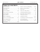
IOM Instructions HBH/V COMPACT TABLE OF CONTENTS Heat Controller, Inc. Model Nomenclature...................................................2 Electrical - Power & Low Voltage Wiring..............22-24 General Information..................................................3-4 Electrical - Thermostat Wiring................................... 25 Physical Data..............................................................5 CXM Controls............................................................
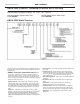
HBH/V COMPACT HEAT CONTROLLER OEM PRICE LIST Heat Controller, Inc. IOM Instructions HBH & HBV COMPACT Horizontal & Vertical HFC-410a Units Entering Water Temperature Range: 20 - 120°F (-6.7 - 48.
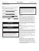
IOM Instructions HBH/V COMPACT Heat Controller, Inc. General Information Safety Warnings, cautions and notices appear throughout this manual. Read these items carefully before attempting any installation, service or troubleshooting of the equipment. DANGER: Indicates an immediate hazardous situation, which if not avoided will result in death or serious injury. DANGER labels on unit access panels must be observed.
Heat Controller, Inc. HBH/V COMPACT IOM Instructions General Information Prepare units for installation as follows: 1. Compare the electrical data on the unit nameplate with ordering and shipping information to verify that the correct unit has been shipped. 2. Keep the cabinet covered with the original packaging until installation is complete and all plastering, painting, etc. is finished. 3. Verify refrigerant tubing is free of kinks or dents and that it does not touch other unit components. 4.
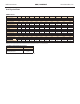
IOM Instructions Heat Controller, Inc. HBH/V COMPACT Unit Physical Data HBH/V Series HB Series 006 009 012 Compressor (1 Each) Factory Charge R410A (oz) 015 018 024 030 036 Rotary 042 048 060 Scroll 17 18.
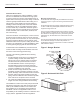
Heat Controller, Inc. IOM Instructions HBH/V COMPACT Horizontal Installation Horizontal Unit Location Units are not designed for outdoor installation. Locate the unit in an INDOOR area that allows enough space for service personnel to perform typical maintenance or repairs without removing unit from the ceiling. Horizontal units are typically installed above a false ceiling or in a ceiling plenum.
IOM Instructions Heat Controller, Inc.
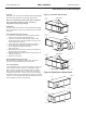
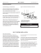
Heat Controller, Inc. IOM Instructions HBH/V COMPACT Field Conversion of Air Discharge Overview Horizontal units can be field converted between side (straight) and back (end) discharge using the instructions below. Note: It is not possible to field convert return air between left or right return models due to the necessity of refrigeration copper piping changes. Figure 4: Left Return Side to Back Return Air Preparation It is best to field convert the unit on the ground before hanging.
IOM Instructions Heat Controller, Inc. HBH/V COMPACT Horizontal Installation Condensate Piping – Horizontal Units Figure 6: Horizontal Condensate Connection Pitch the unit toward the drain as shown in Figure 2 to improve the condensate drainage. On small units (less than 2.5 tons/8.8 kW), insure that unit pitch does not cause condensate leaks inside the cabinet. Install condensate trap at each unit with the top of the trap positioned below the unit condensate drain connection as shown in Figure 6.
Heat Controller, Inc. IOM Instructions HBH/V COMPACT Vertical Installation Vertical Unit Location Units are not designed for outdoor installation. Locate the unit in an INDOOR area that allows enough space for service personnel to perform typical maintenance or repairs without removing unit from the mechanical room/closet. Vertical units are typically installed in a mechanical room or closet.
IOM Instructions Heat Controller, Inc. HBH/V COMPACT Vertical Installation Sound Attenuation for Vertical Units Sound attenuation is achieved by enclosing the unit within a small mechanical room or a closet. Additional measures for sound control include the following: 1. Mount the unit so that the return air inlet is 90° to the return air grille. Refer to Figure 9. Install a sound baffle as illustrated to reduce line-of sight sound transmitted through return air grilles. 2.
Heat Controller, Inc. IOM Instructions HBH/V COMPACT Piping Installation Installation of Supply and Return Piping Follow these piping guidelines. 1. Install a drain valve at the base of each supply and return riser to facilitate system flushing. 2. Install shut-off / balancing valves and unions at each unit to permit unit removal for servicing. 3. Place strainers at the inlet of each system circulating pump. 4. Select the proper hose length to allow slack between connection points.
IOM Instructions HBH/V COMPACT Heat Controller, Inc. Water-Loop Heat Pump Applications Commercial Water Loop Applications Commercial systems typically include a number of units connected to a common piping system. Any unit plumbing maintenance work can introduce air into the piping system; therefore air elimination equipment is a major portion of the mechanical room plumbing.
Heat Controller, Inc. IOM Instructions HBH/V COMPACT Ground-Loop Heat Pump Applications CAUTION! CAUTION! The following instructions represent industry accepted installation practices for closed loop earth coupled heat pump systems. Instructions are provided to assist the contractor in installing trouble free ground loops. These instructions are recommendations only. State/provincial and local codes MUST be followed and installation MUST conform to ALL applicable codes.
IOM Instructions Ground-Loop Heat Pump Applications Figure 13: Typical Ground-Loop Application HBH/V COMPACT Heat Controller, Inc.
IOM Instructions Heat Controller, Inc. HBH/V COMPACT Ground-Water Heat Pump Applications Water Coil Low Temperature Limit Setting For all open loop systems the 30°F [-1.1°C] FP1 setting (factory setting-water) should be used to avoid freeze damage to the unit. See “Low Water Temperature Cutout Selection” in this manual for details on the low limit setting.
Heat Controller, Inc. IOM Instructions HBH/V COMPACT Water Quality Standards Table 3: Water Quality Standards WaterÊQuality Parameter HX Material Closed Recirculating OpenÊLoopÊandÊRecirculatingÊWell ScalingÊPotentialÊ-ÊPrimaryÊMeasurement AboveÊtheÊgivenÊlimits,ÊscalingÊisÊlikelyÊtoÊoccur.ÊÊScalingÊindexesÊshouldÊbeÊcalculatedÊusingÊtheÊlimitsÊbelow pH/CalciumÊHardness Method All - pHÊ<Ê7.
IOM Instructions HBH/V COMPACT Heat Controller, Inc. Electrical - Line Voltage Electrical - Line Voltage All field installed wiring, including electrical ground, must comply with the National Electrical Code as well as all applicable local codes. Refer to the unit electrical data for fuse sizes. Consult wiring diagram for field connections that must be made by the installing (or electrical) contractor.
Heat Controller, Inc. IOM Instructions HBH/V COMPACT Electrical - Line Voltage Table 4a: HB Series Electrical Data - (Standard 60Hz Units) HB Model Voltage Code Rated Voltage Voltage Min/ Max QTY RLA 006 1 208-230/60/1 197/254 1 009 1 208-230/60/1 197/254 1 012 1 208-230/60/1 197/254 1 208-230/60/1 8 265/60/1 1 8 015 018 024 030 036 042 048 060 LRA Fan Motor FLA Total Unit FLA Min Circuit Amp Max Fuse/ HACR 3.3 17.7 0.40 3.7 4.5 15 5.6 22.2 0.80 6.4 7.
IOM Instructions Heat Controller, Inc. HBH/V COMPACT Table 4b: HB Series Electrical Data - (Standard 60Hz Units High Static) HB Model 015 018 024 030 036 042 048 060 Voltage Code Rated Voltage Voltage Min/ Max LRA Fan Motor FLA Total Unit FLA Min Circuit Amp Max Fuse/ HACR QTY RLA 1 208-230/60/1 197/254 1 8 265/60/1 239/292 1 6.0 29.0 1.00 7.0 8.5 15 5.4 28.0 0.86 6.3 7.6 15 1 208-230/60/1 197/254 8 265/60/1 239/292 1 7.2 33.0 1.50 8.7 10.5 15 1 5.9 28.
Heat Controller, Inc. HBH/V COMPACT IOM Instructions Electrical - Power Wiring WARNING! WARNING! Disconnect electrical power source to prevent injury or death from electrical shock. CAUTION! CAUTION! Use only copper conductors for field installed electrical wiring. Unit terminals are not designed to accept other types of conductors. Electrical - Line Voltage All field installed wiring, including electrical ground, must comply with the National Electrical Code as well as all applicable local codes.
IOM Instructions HBH/V COMPACT Heat Controller, Inc. Electrical - Power & Low Voltage Wiring Blower Speed Selection – Units with PSC Motor PSC (Permanent Split Capacitor) blower fan speed can be changed by moving the blue wire on the fan motor terminal block to the desired speed as shown in Figure 16. Most Heat Controller units are shipped on the medium speed tap. Consult submittal data or engineering design guide for specific unit airflow tables.
Heat Controller, Inc. IOM Instructions HBH/V COMPACT Electrical - Low Voltage Wiring Figure 19: Accessory Wiring CXM PCB Accessory Connections A terminal paralleling the compressor contactor coil has been provided on the CXM control. Terminal “A” is designed to control accessory devices, such as water valves. Note: This terminal should be used only with 24 Volt signals and not line voltage. Terminal “A” is energized with the compressor contactor.
IOM Instructions HBH/V COMPACT Heat Controller, Inc. Electrical - Thermostat Wiring Thermostat Installation The thermostat should be located on an interior wall in a larger room, away from supply duct drafts. DO NOT locate the thermostat in areas subject to sunlight, drafts or on external walls. The wire access hole behind the thermostat may in certain cases need to be sealed to prevent erroneous temperature measurement.
Heat Controller, Inc. IOM Instructions HBH/V COMPACT CXM Controls CXM Control For detailed control information, see CXM Application, Operation and Maintenance manual. Field Selectable Inputs Test mode: Test mode allows the service technician to check the operation of the control in a timely manner. By momentarily shorting the test terminals, the CXM control enters a 20 minute test mode period in which all time delays are sped up 15 times.
IOM Instructions HBH/V COMPACT Heat Controller, Inc. Safety Features Safety Features – CXM Control The safety features below are provided to protect the compressor, heat exchangers, wiring and other components from damage caused by operation outside of design conditions. compressor run cycle to be recognized as a FP1 fault. The FP1 input is bypassed for the initial 60 seconds of a compressor run cycle. FP1 is set at the factory for one try.
Heat Controller, Inc. HBH/V COMPACT IOM Instructions CXM Controls b) In cooling mode with compressor energized, FP1 is greater than 125°F [52°C] for 30 continuous seconds, or: c) In cooling mode with compressor energized, FP2 is less than 40°F [4.5°C] for 30 continuous seconds. If a UPS condition occurs, the control will immediately go to UPS warning. The status LED will remain on as if the control is in normal mode. Outputs of the control, excluding LED and alarm relay, will NOT be affected by UPS.
IOM Instructions Heat Controller, Inc. HBH/V COMPACT UNIT STARTING AND OPERATING CONDITIONS Operating Limits Environment – Units are designed for indoor installation only. Never install units in areas subject to freezing or where humidity levels could cause cabinet condensation (such as unconditioned spaces subject to 100% outside air). Power Supply – A voltage variation of +/– 10% of nameplate utilization voltage is acceptable.
Heat Controller, Inc. HBH/V COMPACT IOM Instructions Piping System Cleaning and Flushing Piping System Cleaning and Flushing Cleaning and flushing the WLHP piping system is the single most important step to insure proper start-up and continued efficient operation of the system. Follow the instructions below to properly clean and flush the system: 1. Insure that electrical power to the unit is disconnected. 2. Install the system with the supply hose connected directly to the return riser valve.
IOM Instructions HBH/V COMPACT CAUTION! CAUTION! To avoid possible damage to a plastic (PVC) piping system, do not allow temperatures to exceed 113°F [45°C]. UNIT AND SYSTEM CHECKOUT Unit and System Checkout BEFORE POWERING SYSTEM, please check the following: UNIT CHECKOUT 8 Balancing/shutoff valves: Insure that all isolation valves are open and water control valves are wired.
Heat Controller, Inc. HBH/V COMPACT IOM Instructions Unit Start-Up Procedure Unit Start-up Procedure 1. Turn the thermostat fan position to “ON”. Blower should start. 2. Balance air flow at registers. 3. Adjust all valves to their full open positions. Turn on the line power to all heat pumps. 4. Room temperature should be within the minimummaximum ranges of table 6. During start-up checks, loop water temperature entering the heat pump should be between 60°F [16°C] and 95°F [35°C]. 5.
IOM Instructions Heat Controller, Inc. HBH/V COMPACT Unit Start-Up Procedure Figure 23: Test Mode Pins Short test pins together to enter Test Mode and speedup timing and delays for 20 minutes. WARNING! WARNING! When the disconnect switch is closed, high voltage is present in some areas of the electrical panel. Exercise caution when working with energized equipment. CAUTION! CAUTION! Verify that ALL water control valves are open and allow water flow prior to engaging the compressor.
Heat Controller, Inc. HBH/V COMPACT IOM Instructions Unit Operating Pressures and Temperatures Operating Pressure/Temperature tables include the following notes: • Airflow is at nominal (rated) conditions; • Entering air is based upon 70°F [21°C] DB in heating and 80/67°F [27/19°C] in cooling; • Subcooling is based upon head pressure at compressor service port; • Cooling air and water values can vary greatly with changes in humidity level.
IOM Instructions HBH/V COMPACT Heat Controller, Inc. Unit Operating Pressures and Temperatures Table 8b: HB Series Typical Unit Operating Pressures and Temperatures (60 Hz-I.P.
Heat Controller, Inc. HBH/V COMPACT IOM Instructions Unit Operating Pressures and Temperatures Table 8c: HB Series Typical Unit Operating Pressures and Temperatures (60 Hz-I.P.
IOM Instructions HBH/V COMPACT Heat Controller, Inc. Unit Operating Pressures and Temperatures Table 8d: HB Series Typical Unit Operating Pressures and Temperatures (60 Hz-I.P. Units) Table 9: Water Temperature Change Through Heat Exchanger Water Flow, gpm [l/m] Rise, Cooling °F, [°C] Drop, Heating °F, [°C] For Closed Loop: Ground Source or Closed Loop Systems at 3 gpm per ton [3.2 l/m per kW] 9 - 12 [5 - 6.7] 4-8 [2.2 - 4.4] For Open Loop: Ground Water Systems at 1.5 gpm per ton [1.
Heat Controller, Inc. HBH/V COMPACT IOM Instructions Preventive Maintenance Water Coil Maintenance (Direct ground water applications only) If the system is installed in an area with a known high mineral content (125 P.P.M. or greater) in the water, it is best to establish a periodic maintenance schedule with the owner so the coil can be checked regularly. Consult the well water applications section of this manual for a more detailed water coil material selection.
IOM Instructions HBH/V COMPACT Functional Troubleshooting Fault Main power Problems Htg Clg Possible Cause X HP Fault-Code 2 High pressure Solution X Green Status LED Off Check Line Voltage circuit breaker and disconnect Check for line voltage between L1 and L2 on the contactor Check for 24VAC between R and C on CXM/DXM Check primary/secondary voltage on transformer Check pump operation or valve operation/setting Check water flow adjust to proper flow rate X Reduced or no water flow in cooling X
Heat Controller, Inc. IOM Instructions HBH/V COMPACT Functional Troubleshooting Only Compressor Runs X X Thermostat wiring Check G wiring at heat pump. Jumper G and R for fan operation. X X Fan motor relay Jumper G and R for fan operation. Check for Line voltage across BR contacts.
Serial Number: ________________________ Packaged Unit Refrigeration Schematic IOM Instructions HBH/V COMPACT Date: ________________________ Heat Controller, Inc. Customer: _____________________________________ Antifreeze: ________________________ Functional Troubleshooting - I.P.
01/2010 04/2009