
User manual


5
Heat Controller, Inc. DXM2 UNIT CONTROLS Application, Operation, & Maintenance Manual
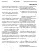
DXM2 Layout and Connections
P1
Alarm
Relay
Comp
Relay
O
Y1
Y2
W
G
C
R
AL1
24Vdc
EH1
EH2
P6
R
C
Off On
JW3
A
OVR
ESD
C
R
NSB
AL2
JW1
Acc1
Relay
Acc2
Relay
H
COM
NC1
NO1
COM
NC2
NO2
P3
CO
RV
RV
LT1
LT1
LT2
LT2
LP
LP
HP
HP
P7
Status
Fault
R
R
CC
CCG
CO
S1
S2
1
12
1
4
e
sU y
rotcaF
(240Vac)
Com
N.O.
Fan Enable
Micro
U1
Off On
P2
COH
COM
AO2
P11
Gnd
T1
P10
T2 T2 T3 T3 T4 T4
T5
P9
T5
T6 T6
A0-1 A0-2
Off On
S3
RV
Relay
CCH
Relay
Test
P5
B-
Gnd
P4
A+ 24V
(240Vac)
Fan Speed
N.O.
N.C.
12V
OUT
Gnd
P8
IN
NC
P12
1 2 3 4
1 2 3 4 5 6 7 8
1 2 3 4 5 6 7 8
Service tool
connection
Communicating
stat connection
Conventional
stat connection
Cabinet
temperature
sensor
(with variable
speed pump)
24V to compressor
load capacity
Use 4 mounting screws #6
Configure
modulating valve
or variable
speed pump
sheet metal screw 1” long
Variable
speed pump
Entering
water temp
Leaving
water temp
Leaving
air temp
Factory low
voltage molex
connection for
electric heat
harness
Factory low
voltage molex
connection for
unit harness
Entering Hot water
Temperature
Compressor Discharge
temperature
ECM Motor
Connection
Confi gure
Modulating Valve
(Optional)