Modular Air Handler Installation Instructions HMB**A*1E, HMB**X*1E, & HMB**V*1E Series IMPORTANT ATTENTION INSTALLERS: It is your responsibility to know this product better than your customer. This includes being able to install the product according to strict safety guidelines and instructing the customer on how to operate and maintain the equipment for the life of the product. Safety should always be the deciding factor when installing this product and using common sense plays an important role as well.
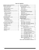
TABLE OF CONTENTS Important Safety Information........................3 General Information...........................................3 Requirements & Codes..............................................3 About the Air Handler.................................................3 Before You Install this Equipment...............................4 Minimum Clearances..................................................4 Locating the Air Handler.............................................
Important SAFETY INFORMATION Please read all information in this manual thoroughly and become familiar with the capabilities and use of this appliance before attempting to service or maintain this unit. Safety markings are used frequently throughout this manual to designate a degree or level of seriousness and should not be ignored. WARNING indicates a potentially hazardous situation that if not avoided, could result in personal injury or death.
Before You Install this Equipment √ This equipment is securely packaged at the time of shipment and upon arrival should be carefully inspected for damage prior to installing the equipment at the job site. Claims for damage (apparent or concealed) should be filed immediately with the carrier. √ it is recommended that the cooling load of the area to be conditioned should be calculated and a system of the proper capacity selected.
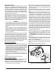
Plenums & Air Ducts • Plenums and air ducts should be installed in accordance with the standards of the National Fire Protection Association Standard for Installation of Air Conditioning Systems (NFPA 90A), Standard for Installation of Residence Type Warm Air Heating and Air Conditioning Systems (NFPA 90B), and all applicable local codes. NFPA publications are available by writing to: National Fire Protection Association, Batterymarch Park, Quincy, ME 02269 or visit www.NFPA.org online.
around penetrations into the air handler, such as for electrical wiring. Air Filters WARNING: Never operate the air handler without a filter or with doors removed. Dust and lint can build up on internal components, resulting in loss of efficiency, equipment damage, and possible fire. HMB Series air handlers are not equipped with filter racking; however, it is strongly recommends that a filter be located in the return air duct system.
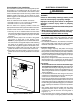
Downflow Installation The HMB Series Modular air handler may be installed in a downflow configuration as shown in Figure 1. Return air must enter through the top of the unit. Upflow Configuration Downflow Configuration Figure 1. Upflow & Downflow Installation Mo dul ar A ir H and le r Rea Upflow Configuration r Br ack et Cas ed 1. Remove the lower front bracket (Figure 3) from the modular unit. Retain the screws for later use. 2.
Horizontal Installation HMB series air handlers are shipped from the factory ready for horizontal left applications and horizontal right applications. The blowers can be installed horizontally in an attic, basement, crawl space or alcove. They can also be suspended from a ceiling in a basement or utility room in either a right to left airflow or left to right airflow. A typical installation of the unit in a suspended horizontal application is shown in Figure 5.
Circuit Breaker Cover Installation The air handler circuit breaker cover is designed to protect the breakers of an installed heater kit from debris and condensation.The cover attaches to the breaker recess of the air handler upper access door using a double-sided adhesive gasket. See Figure 6. The heater kit circuit breaker toggles are still accessible and can be switched with the cover in place. There are 2 different circuit breaker cover sizes: • 2-breaker cover for 2, 2.5, 3, & 3.5 ton air handlers.
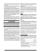
a conduit connector for connecting the supply wires to the unit. Aluminum supply wire may be used if a heater kit is installed. • If replacing any of the original wires supplied with the unit, the replacement wire must be copper wire consisting of the same gauge and temperature rating. • Provide power supply for the unit in accordance with the unit wiring diagram, and the unit rating plate. Use UL listed conduit and conduit connectors for connecting the supply wires to the unit and for proper grounding.
If a heater kit is not installed: 1. Remove the 2 wire plug of the air handler by cutting the wires and discarding the plug. 2. Strip the ends of the 2 air handler wires and connect to the line-voltage leads with the 2 wire nuts provided. Electronic Air Cleaner (EAC) The unit has an output to power an electronic air cleaner when the blower is running. This output is rated to 1.0 amp at 208/240V. Humidifier The unit has an output to power a humidifier when the blower is running. This output is rated to 1.
Blower Configurations Selecting Minimum Electric Heat Airflow The minimum electric heat airflow setting controls the minimum air flow that will be produced whenever electric heater kits are used. When the electric heater kit is energized along with a heat pump, the airflow may be higher depending on the basic cooling/heat-pump airflow setting. The minimum electric heat airflow is selected by the red blower wire on 3-speed models or setting switches 1,2,3 & 4 on HMB**X*1E models.
• For maximum capacity and energy efficiency, select an airflow at or near the top of the range for that nominal capacity. See Table 7 (page 19). • For maximum dehumidification, select an airflow near the middle or bottom of the range for that nominal capacity. Additional information on humidity control can be found in the Humidistat and Delay Setting sections.
Blower Fan Wheel Inspect the blower wheel blades for accumulations of dirt and clean if necessary. Inspect mounting nut for tightness. Blower Motor & Assembly Inspect the blower assembly and motor mounting brackets for tightness and corrosion. Correct deficiencies if necessary. The blower motor contains sealed bearings and under normal operating conditions, no maintenance is necessary for the life of the equipment.
Figures & Tables 3/4 TYP. 3/4 TYP. TOP VIEW 12 7/8 Ø1 1/8” K.O. (TYP.) 1 1/4 "A" Ø 1 7/8 K.O. 2 7/8 1 3/4 1 1/4 3 1/4 2 5/8 1 7/8 1” 1 7/8 3 1/2 5 1/2 Ø1 1/8” K.O. Ø 7/8 K.O. Ø1 3/4” K.O. "B" FRONT VIEW LEFT SIDE RIGHT SIDE "C" 22” BOTTOM VIEW Furnace Size (BTUH) Dimension A Dimension B Dimension C 24K & 30K 36K & 42K 48K & 60K 12-3/4 12-3/4 18-1/4 24-3/4 24-3/4 27-1/2 14-1/4 17-1/2 21 Figure 8.
Outlet Heater Box Heating Element Assembly Transformer Control Board Blower Wheel Blower Door Blower Housing Rear Bracket Motor Control Board Lower Front Bracket Motor Mount Kit Front Joining Bracket Coil Assembly Figure 9.
BLOWER PERFORMANCE DATA HMB**A*1E Airflow Data Dry Coil ESP HMB24AA1E 0.10 0.20 0.30 0.40 0.50 0.60 0.70 0.80 Low Corrected ESP1 685 645 0.07 605 0.19 565 0.30 515 0.42 465 0.53 405 0.65 345 0.76 Med 860 825 Corrected ESP1 High 1070 1025 780 735 680 625 565 500 0.11 0.23 0.36 0.48 0.60 0.72 975 Corrected ESP1 Low 850 Corrected ESP1 HMB36AA1E Med 1120 1275 Low 995 HMB36AB1E Med 1335 1470 1035 755 705 645 580 510 0.27 0.38 0.50 0.62 0.
Cooling or Heating Airflow (CFM) Switch Settings 0 = OFF, 1 = ON 1/5 2/6 3/7 4/8 HMB36XA1E Dry Coil ESP 0.1 0.2 0.3 0.4 0.5 0.6 0.7 0.
Nominal Electic Heat KW Furnace Models 5 8 10 15 20 HMB36XA1E 800 900 1000 1300 N/A HMB48XB1E HMB60XC1E 900 1000 1000 1100 1100 1200 1300 1400 1500 1600 NOTE: See Table 6 for appropriate switch settings for these airflows. Table 6.
Cooling Airflow A/B Switch Setting 0 = OFF, 1 = ON HMB36VA1E 0 0 0 0 0 0 0 0 0 0 0 0 0 0 0 0 Heating Airflow COOL Switch Setting 0 = OFF, 1 = ON 5 6 7 8 0 0 0 0 0 0 0 0 1 1 1 1 1 1 1 1 0 0 0 0 1 1 1 1 0 0 0 0 1 1 1 1 0 0 1 1 0 0 1 1 0 0 1 1 0 0 1 1 0 1 0 1 0 1 0 1 0 1 0 1 0 1 0 1 Airflow (CFM) A/B Switch Setting 0 = OFF, 1 = ON Heater Kit Installed (KW) Airflow (CFM) 525 560 600 625 700 750 800 850 875 890 930 950 1000 1050 1125 1200 0 0 0 0 0 0 0 0 0 5 8 10 15 20 25 30 600 800 1000 1000
Electrical DATA & diagrams HMB**A*1E SERIES 240 VAC, 50 & 60 Hz, Single Phase Circuit C Single Circuit Circuit A Circuit B Circuit C Single Circuit Circuit A Circuit B Circuit C Single Circuit Circuit B Circuit B HMB60AC1E (2000CFM) MOP Circuit A HMB48AC1E (1600CFM) MCA Single Circuit HMB36AA1E & HMB36AB1E (1200CFM) 1.6 26.6 41.2 51.6 51.6 25 2.6 27.6 42.2 52.6 52.6 25.0 52.6 50.0 3.1 28.1 42.7 53.1 53.1 53.1 5 30 44.
Thermostat Thermostat Thermostat WYG R WY GR Y1 W2 W/E Y2 G R NOTE: Jumper W1 & W2 together if not using W2 on thermostat Air Handler Y1 Y1 W2 W2 W1 Air Conditioner W1 Y Y/Y2 R R C Typical Air Conditioner with Standard Air Handler R C Thermostat NOTE: Jumper W1 & W2 together if not using W2 on thermostat NOTE: Jumper between W2 & E is required when no OD T-Stat is used.
P2 R C G W 3A Fuse Y BLWDTC BLWDTC_R L2 L1 EAC COOL HEAT LED 1 HEATER P1 Figure 11. Single Stage Control Board (HMB**A*1E Series) R G Y/2Y O W1 W2 Y1 L 3A Fuse C P3 EAC HUM L2 P2 LED 1 HEATER P1 Figure 12.
TEST PORT R W1 NOT USED FAN SPEED GREEN RED OFF ON TWIN DEHUM Y1 C EXPANSION PORT 1 2 3 4 5 6 78 HEAT COOL STATUS BLOWER MOTOR Figure 13. Fixed Speed Motor Control Board (HMB**X*1E Series) STATUS LIGHTS L2-OUT L2-IN GREEN RED Y/Y2 RED OUTPUTS W L1-IN Y1 L1-OUT H 2 3 4 5 6 78 HEAT Y1 COOL SENSOR C GND EXPANSION PORT BLOWER MOTOR Figure 14.
Field Wiring Factory Wiring: Low Voltage High Voltage Legend IF BOARD EQUIPPED WITH BLWDTC TERMINAL BLACK Air Handler R BLW DTC YELLOW W G C HEATER PLUG 7654321 Y R WHITE GREEN GRAY RED WIRING DIAGRAM RELAY 4-PIN PLUG (18) RELAY Figure 15. Wiring Diagram for HMB**A*1E Series Air Handler 25 L1 L2 R C L2 L1 HEAT COOL EAC 2 1 RED BLACK CAP. BROWN BROWN RED 3-SPEED MOTOR 1=COM 2=CAP. 3=CAP.
240 24 V C GRAY RED Figure 16. Wiring Diagram for HMB**X*1E Series Air Handler TWIN R C Y DEHUM L1 Field Wiring Factory Wiring: Low Voltage High Voltage R L1 L2 C R BLACK MOTOR EXPANSION TEST WHITE HARNESS 1 2 3 4 5 6 HARNESS 6-PIN PLUG 1 2 3 4 5 6 WHITE BLACK MOTOR GREEN 9-PIN HOUSING 9-PIN PLUG 6-PIN PLUG 7110760 0510 NOTES: 1. The blower motor speed tap connection may not be as shown. See the Installation Instructions. 2. Disconnect all power before servicing. 3.
L2 HUM EAL HARNESS BLACK RED Field Wiring Factory Wiring: Low Voltage High Voltage Legend R 24 V WHITE BLACK COM RED C TRANSFORMER 240 208 L1 L2 C R EXPANSION NOTES: 1. The blower motor speed tap connection may not be as shown. See the Installation Instructions. 2. Disconnect all power before servicing. 3. Transformer may havea dual voltage primary tap. Match the tap position with the supply voltage used. 4. If the internal wiring is replaced, use only 105°C copper wire of the same gauge.
Control Signal & MODE Operation Total KW 5 KW Board Action Stage 1 Heat on instantly Heat blower on after 3 second delay Stage 1 Heat on instantly 10 KW Heat blower on after 3 second delay Stage 2 Heat on after 5 seconds delay Stage 1 Heat on instantly W EHEAT On 15 KW Heat blower on after 3 second delay Stage 2 Heat on after 5 seconds delay Stage 3 Heat on after 10 seconds delay Stage 1 Heat on instantly Heat blower on after 3 second delay 20 KW Stage 2 Heat on after 5 seconds delay Stage 3 Heat
Control Signal & MODE Operation Total KW 5 KW 10 KW Board Action Stage 1 Heat on instantly Heat blower on after 3 second delay Stage 1 Heat on instantly Heat blower on after 3 second delay Stage 1 Heat on instantly W1 only EHEAT On 15 KW Heat blower on after 3 second delay Stage 2 Heat on after 5 second delay Stage 1 Heat on instantly 20 KW Heat blower on after 3 second delay Stage 2 Heat on after 5 second delay Stage 3 Heat on after 10 second delay Heat stages off instantly Blower off after 15 sec
Control Signal & MODE Operation Total KW 5 KW 10 KW Board Action Stage 1 Heat on instantly Cool blower on after 3 second delay Stage 1 Heat on instantly Cool blower on after 3 second delay Stage 1 Heat on instantly W1 & Y/Y2 AUX HEAT On 15 KW Cool blower on after 3 second delay Stage 2 Heat on after 5 seconds delay Stage 1 Heat on instantly 20 KW Cool blower on after 3 second delay Stage 2 Heat on after 5 seconds delay Stage 3 Heat on after 10 seconds delay Heat stages off instantly Heat blower tur
INSTALLATION / PERFORMANCE CHECK LIST INSTALLER NAME: CITY: ELECTRICAL SYSTEM: STATE: YES NO Line voltage polarity correct? YES NO Supply Voltage: ___________________________________(V) INSTALLATION ADDRESS: CITY: Electrical connections tight? STATE: Has the thermostat been calibrated? YES NO Is the thermostat level? YES NO Is the heat anticipator setting correct? YES NO UNIT MODEL # ATTENTION INSTALLERS: UNIT SERIAL # Minimum clearances per page 4? YES NO Is the unit properly ins