INSTALLATION, OPERATION & MAINTENANCE MANUAL R-410A Water-to-Water Series: HWW Water-Source Heat Pumps Heat Controller, Inc. • 1900 Wellworth Ave. • Jackson, MI 49203 • (517)787-2100 • www.heatcontroller.
Installation & Operation WATER-TO-WATER (HWW) SERIES Heat Controller, Inc. TABLE OF CONTENTS Model Nomenclature...................................................2 Electrical - Line Voltage........................................14,16 Storage........................................................................4 Electrical - Accessories.............................................15 Pre-Installation............................................................4 Water Valve Wiring....................
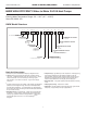
Heat Controller, Inc. Installation & Operation WATER-TO-WATER (HWW) SERIES HEAT CONTROLLER OEM PRICE LIST HWW Water-to-Water HFC-410a HWWHIGH HIGHEFFICIENCY EFFICIENCY Water-to-Water R-410AHeat HeatPumps Pumps Entering Water Temperature Range: 20 - 110°F (-6.7 - 43.
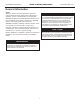
Installation & Operation WATER-TO-WATER (HWW) SERIES Heat Controller, Inc. General Information Safety � WARNING! � Warnings, cautions and notices appear throughout this manual. Read these items carefully before attempting any installation, service or troubleshooting of the equipment. WARNING! All refrigerant discharged from this unit must be recovered WITHOUT EXCEPTION.
Heat Controller, Inc. WATER-TO-WATER (HWW) SERIES Installation & Operation General Information Inspection 3. Verify refrigerant tubing is free of kinks or dents and that it does not touch other unit components. Upon receipt of the equipment, carefully check the shipment against the bill of lading. Make sure all units have been received. Inspect the carton or crating of each unit, and inspect each unit for damage.
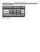
Installation & Operation WATER-TO-WATER (HWW) SERIES Unit Physical Data Model 036 060 120 4.5 [2.04] 5.5 [2.49] 5.5 [2.49] Residential 1" Swivel 1” Swivel Commercial 3/4” IPT 1” IPT Residential 1" Swivel 1” Swivel Commercial 1/2” IPT 1/2” IPT Weight - Operating (lbs) [kg] 348 [158] 360 [163] 726 [329] Weight - Packaged (lbs) [kg] 373 [169] 385 [175] 770 [349] 0.96 (3.64) 1.33 (5.04) 2.65 (10.
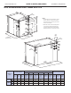
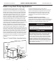
Heat Controller, Inc. Installation & Operation WATER-TO-WATER (HWW) SERIES Unit Dimensional Data: HWW 036–120 A B B 1.0 5 (2.5 cm) 3 F 2 L K G H J C D 2. While clear access to all removable panels is not required, installer should take care to comply with all building codes and allow adequate clearance for future field services. 7.3 (18.5 cm) Optional Service Access Required Service Access A B 1.8 (4.6 cm) A 1.0 5 (2.
Installation & Operation Heat Controller, Inc. WATER-TO-WATER (HWW) SERIES Unit Installation HWW Unit Location Locate the unit in an indoor area that allows easy removal of access panels, and has enough space for service personnel to perform maintenance or repair. Provide sufficient room to make water and electrical connections.. Any access panel screws that would be difficult to remove after the unit is installed should be removed prior to setting the unit.
Heat Controller, Inc. Installation & Operation WATER-TO-WATER (HWW) SERIES Piping Installation Load Plumbing Installation HWW Unit Load Plumbing chlorine/bromine fluid applications. The applications are too varied to describe in this document. However, some basic guidelines will be presented. Much of the discussions on water loop applications would be valid for the load plumbing discussion as well.
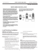
Installation & Operation WATER-TO-WATER (HWW) SERIES Heat Controller, Inc. Water-Loop Heat Pump Applications Commercial systems typically include a number of units plumbed to a common piping system. Any unit plumbing maintenance work can introduce air into the piping system, therefore air elimination equipment is a major portion of the mechanical room plumbing.
Heat Controller, Inc. Installation & Operation WATER-TO-WATER (HWW) SERIES Ground-Water Heat Pump Applications Typical open loop piping is shown in Figure 3 [See Page 11]. Shut off valves should be included in case of servicing. Boiler drains or other valves should be ‘tee’d’ into the line to allow acid flushing of just the heat exchanger. Pressure temperature plugs should be used so that flow and temperature can be measured. Piping materials should be limited to PVC SCH80 or copper.
Installation & Operation WATER-TO-WATER (HWW) SERIES Heat Controller, Inc. Ground-Water Heat Pump Applications In areas with extremely hard water, the owner should be informed that the heat exchanger may require occasional acid flushing. � CAUTION! � Low temperature limit system will not allow leaving load water temperature (cooling mode) or leaving source water temperature (heating mode) to be below 42°F [5.6°C].
Heat Controller, Inc. Installation & Operation WATER-TO-WATER (HWW) SERIES Ground-Loop Heat Pump Applications polyethylene fusion for inground sections of the loop. � CAUTION! � Galvanized or steel fittings should not be used at any time due to their tendency to corrode. All plastic to metal threaded fittings should be avoided due to their potential to leak in earth coupled applications and a flanged fitting substituted.
Installation & Operation WATER-TO-WATER (HWW) SERIES Figure 1: Typical Figure 4: Ground-Loop TypicalApplication Ground-Loop Application Unit Power Disconnect Air Pad or Extruded polystyrene insulation board Thermostat Wiring 13 Heat Controller, Inc.
Heat Controller, Inc. Installation & Operation WATER-TO-WATER (HWW) SERIES Electrical-Line Voltage � CAUTION! � � WARNING! � Disconnect electrical power source to prevent injury or death from electrical shock. Use only copper conductors for field installed electrical wiring. Unit terminals are not designed to accept other types of conductors.
Installation & Operation Heat Controller, Inc. WATER-TO-WATER (HWW) SERIES Electrical-Accessories Accessory Connections 24 Volt Accessory Wiring for Units Size 036 and 060 A terminal paralleling the compressor contactor coil has been provided on the CXM control of the HWW line. “A” has been provided to control accessory devices, such as water valves, electronic air cleaners, humidifiers, etc. Note: This terminal must be used only with 24 Volt signals and not line voltage Water operates signals.
Grnd L2 HWG PB2 T1 T2 Low Voltage Connector L1 Heat Controller, Inc. WATER-TO-WATER (HWW) SERIES CXM Control Yellow Electrical-Line Voltage Circ Brkr Install HWG Pump Power after insuring water is in HWG circuit Contactor -C All field installed wiring, including electrical ground, must Loop PB1 Grnd T2 comply with the National Electrical Code as well as all apT1 L3 plicable local codes.
Installation & Operation Heat Controller, Inc. WATER-TO-WATER (HWW) SERIES Electrical-Low Voltage Figure 7b: HWW120 Low Voltage Field Wiring (CXM board shown) Thermostat Connections The aquastat/thermostat should be wired directly to the CXM board as shown in Figure 7a for HWW036-060 and Figure 7b for the HWW120. Note the HWW second stage is wired directly to the CXM #2. L1 L2 L3 Contactor -CC1 Grnd Figure 7a.
Heat Controller, Inc.
Installation & Operation WATER-TO-WATER (HWW) SERIES Typical Wiring Diagram Single Phase: HWW036-060 Units with CXM Controller 19 Heat Controller, Inc.
Heat Controller, Inc. Installation & Operation WATER-TO-WATER (HWW) SERIES CXM Controls: For detailed control information, see the CXM Application, Operation and Maintenance manual. DIP switch 4: If Set to “EH2 normal,” EH2 will operate as standard electric heat output. Field Selectable Inputs On = EH2 Normal. Test mode: Test mode allows the service technician to check the operation of the control in a timely manner.
Installation & Operation WATER-TO-WATER (HWW) SERIES Heat Controller, Inc. Safety Features: CXM Controls The safety features below are provided to protect the compressor, heat exchangers, wiring and other components from damage caused by operation outside of design conditions. will go into lockout mode once the FP1 fault has occurred.
Heat Controller, Inc. Installation & Operation WATER-TO-WATER (HWW) SERIES Safety Features c) In cooling mode with compressor energized, FP2 is less than 40°F [4.5°C] for 30 continuous seconds. If a UPS condition occurs, the control will immediately go to UPS warning. The status LED will remain on as if the control is in normal mode. Outputs of the control, excluding LED and alarm relay, will NOT be affected by UPS. The UPS condition cannot occur during a compressor off cycle.
Installation & Operation WATER-TO-WATER (HWW) SERIES Heat Controller, Inc. Piping Systems Cleaning & Flushing Cleaning and flushing of the WLHP piping system is the single most important step to ensure proper start-up and continued efficient operation of the system. � CAUTION! � To avoid possible damage to a plastic (PVC) piping system, do not allow temperatures to exceed 110°F [43°C]. Follow the instructions below to properly clean and flush the system: 1.
Heat Controller, Inc. WATER-TO-WATER (HWW) SERIES Installation & Operation Unit & System Checkout BEFORE POWERING SYSTEM, please check the following: � WARNING! � q System pH: System water pH is 6 - 8.5. Proper pH promotes longevity of hoses and fittings. q System Flushing: Verify all hoses are connected end to end when flushing to ensure debris bypasses unit heat exchanger and water valves etc.
Installation & Operation WATER-TO-WATER (HWW) SERIES Heat Controller, Inc. Unit Start Up Procedures Table 5: Water Temperature Change Through Source Heat Exchanger � WARNING! � When the disconnect switch is closed, high voltage is present in some areas of the electrical panel. Exercise caution when working with energized equipment. 1. Adjust all valves to their full open position. Turn on the line power to all heat pump units. 2. Operate each unit in the cooling cycle.
Heat Controller, Inc.
Installation & Operation Heat Controller, Inc. WATER-TO-WATER (HWW) SERIES Operating Pressures TMW036-120 (TMW120 Per Circuit) (60 Hz I-P Units) Source Entering Water Temp °F Source Water Flow GPM/ton 1.5 50 2.3 3.0 1.5 80 2.3 3.0 1.5 110 2.3 3.0 Cooling Load EWT °F @ 1.5-3.
Heat Controller, Inc. Installation & Operation WATER-TO-WATER (HWW) SERIES Operating Pressures TMW036-120 (TMW120 Per Circuit) (60 Hz I-P Units) Source Entering Water Temp °F 20 Source Water Flow GPM/ton 3.0 1.5 50 2.3 3.0 1.5 80 2.3 3.0 Heating Load EWT °F @ 1.5-3.
Installation & Operation WATER-TO-WATER (HWW) SERIES Heat Controller, Inc. Preventative Maintenance Heat Exchanger Maintenance – (Direct Ground Water Applications Only) If the installation is performed in an area with a known high mineral content (125 P.P.M. or greater) in the water, it is best to establish with the owner a periodic maintenance schedule so the coil can be checked regularly. Consult the well water applications section of this manual for a more detailed water coil material selection.
Heat Controller, Inc.
11/2010 04/2009