
Quick Start Manual

16
Heat Controller, Inc. WATER-TO-WATER (HWW) SERIES Installation & Operation
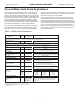
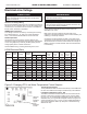
Electrical-Line Voltage
All eld installed wiring, including electrical ground, must
comply with the National Electrical Code as well as all ap-
plicable local codes.
Refer to the unit wiring diagrams for fuse sizes and a sche-
matic of the eld connections which must be made by the
installing (or electrical) contractor.
Consult the unit wiring diagram located on the inside of
the compressor access panel to ensure proper electrical
hookup.
All nal electrical connections must be made with a length of
exible conduit to minimize vibration and sound transmission
to the building.
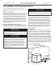
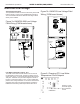
208 Volt Operation
All 208-230 Volt units are factory wired for 208 Volt. The
transformers may be switched to 230V operation as illustrat-
ed on the wiring diagram. By switching the Red (230V) and
the Orange (208V) at the contactor terminal L2.
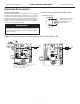
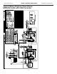
Capacitor
Transformer
CXM Control
Circ Brkr
Contactor -CC
Low Voltage
Connector
CB
HWG PB2
T2
T1
Rev .: 01/21/09B
Unit Power Supply
See electrical table for
wire and breaker size
L2
L1
External Pump
Power Supply
See electrical table for
wire and breaker size
Grnd
Loop PB1
T2
T1
Install HWG Pump
Power after insuring
water is in HWG circuit
Yellow
Grnd
L2
L3
L1
Contactor -C
Grnd
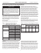
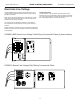
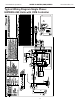
HWW036-060 Series Line Voltage Field Wiring Commercial Class (3 phase shown)
HWW120 Series Line Voltage Field Wiring Commercial Class