
Quick Start Manual


22
Heat Controller, Inc. WATER-TO-WATER (HWW) SERIES Installation & Operation
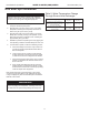
Safety Features
c) In cooling mode with compressor energized,
FP2 is less than 40°F [4.5°C] for 30 continuous
seconds.
If a UPS condition occurs, the control will immediately go to
UPS warning. The status LED will remain on as if the control
is in normal mode. Outputs of the control, excluding LED
and alarm relay, will NOT be affected by UPS. The UPS
condition cannot occur during a compressor off cycle. During
UPS warning, the alarm relay will cycle on and off. The cycle
rate will be “on” for 5 seconds, “off” for 25 seconds, “on” for
5 seconds, “off” for 25 seconds, etc.
UPS warning code = 8
Swapped FP1/FP2 thermistors: During test mode, the con-
trol monitors to see if the FP1 and FP2 thermistors are in the
appropriate places. If the control is in test mode, the control
will lockout with code 9 after 30 seconds if:
a) The compressor is on in the cooling mode and
the FP1 sensor is colder than the FP2 sensor, or:
b) The compressor is on in the heating mode and
the FP2 sensor is colder than the FP1 sensor.
Swapped FP1/FP2 thermistor code = 9.
Diagnostic Features
The LED on the CXM board advises the technician of the
current status of the CXM control. The LED can display
either the current CXM mode or the last fault in memory if in
test mode. If there is no fault in memory, the LED will ash
Code 1 (when in test mode).
CXM Control Start-up Operation
The control will not operate until all inputs and safety con-
trols are checked for normal conditions. The compressor will
have a 5 minute anti-short cycle delay at power-up. The rst
time after power-up that there is a call for compressor, the
compressor will follow a 5 to 80 second random start delay.
After the random start delay and anti-short cycle delay, the
compressor relay will be energized. On all subsequent com-
pressor calls, the random start delay is omitted.
CXM Controls
Unit Commissioning & Operating Conditions
Environment – This unit is designed for indoor installation only.
Do not install in an area subject to freezing or where humidity
levels can cause cabinet condensation.
Power Supply – A voltage variation of +/- 10% of nameplate
utilization voltage is acceptable.
Operation and performance is primarily dependent upon water
temperatures, water ow rates and ambient air temperature. This
water to water heat pump is capable of operating over a wide
temperature range and with ow rates of between 1.5 GPM (.1
l/s) and 3 GPM (.19 l/s) per ton, however usually no more than
one of these factors may be at a minimum or maximum level at
a time.
The commissioning table indicates water temperatures which are
suitable for initial unit commissioning in an environment where
the ow rate and water temperature is not yet stable and to avoid
nuisance shut down of the units freeze and refrigerant pressure
safeties.
The operating Table 4 indicates the maximum and minimum
ranges of the unit.
For more specic unit performance reference the product
catalog, the submittal data sheets or contact your supplier for
assistance.
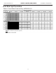
BUILDING COMMISSIONING
Cooling Heating
Unit Size 036 060/120 036 060/120
Source Min/Max 50/110 50/120 30/80 30/80
Load Min/Max 60/80 60/90 60/120 60/120
Ambient Min/Max 45/110 39/85
BUILDING OPERATING
COOLING HEATING
Unit Size 036 060/120 036 060/120
Source Min/Max 50/120 50/120 20/80 20/80
Load Min/Max 50/90 50/90 60/130 60/130
Ambient Min/Max 45/110 39/85
Table 4: Building Commissioning