
user manual

6
• Theoutdoorunitrequiresbothpowerandcontrolcircuit
electrical connections. Refer to the wiring diagram /
schematic for identification and location of outdoor unit
field wiring interfaces (Figure 11, page 17). Make all
electrical connections in accordance with all applicable
codes and ordinances.
• Overcurrentprotectionmustbeprovidedatthebranch
circuit distribution panel and sized as shown on the unit
rating label and according to applicable local codes.
See the unit rating plate for minimum circuit ampacity
and maximum overcurrent protection limits.
• Providepowersupplyfortheunitinaccordancewiththe
unit wiring diagram, and the unit rating plate. Connect
the line-voltage leads to the terminals on the contactor
inside the control compartment.
• Useonlycopperwireforthelinevoltagepowersupply
to this unit as listed in Table 1 (page 5). Use proper
code agency listed conduit and a conduit connector
for connecting the supply wires to the unit. Use of rain
tight conduit is recommended.
• 208/230Voltunitsareshippedfromthefactorywired
for 230 volt operation. For 208V operation, remove the
lead from the transformer terminal marked 240V and
connect it to the terminal marked 208V.
• Optionalequipmentrequiringconnectiontothepower
or control circuits must be wired in strict accordance
of the NEC (ANSI/NFPA 70), applicable local codes,
and the instructions provided with the equipment.
Grounding
WARNING:
The unit cabinet must have an uninterrupted or
unbroken electrical ground to minimize personal
injury if an electrical fault should occur. Do not
use gas piping as an electrical ground
!
This unit must be electrically grounded in accordance
with local codes or, in the absence of local codes, with
the National Electrical Code (ANSI/NFPA 70) or the CSA
C22.1 Electrical Code. Use the grounding lug provided in
the control box for grounding the unit.
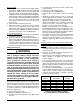
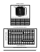
Table 2. Thermostat Wire Gauge
Thermostat
Wire Gauge
Recommended T-Stat Wire
Unit to T-Stat (Length in FT)
2-Wire
(Heating)
5-Wire
(Heating/Cooling)
24 55 25
22 90 45
20 140 70
18 225 110
Thermostat Connections
• Thermostatconnectionsshouldbemadeinaccordance
with the instructions supplied with the thermostat and
the indoor equipment.
• Theoutdoorunitisdesignedtooperatefroma24VAC
Class II control circuit. The control circuit wiring must
comply with the current provisions of the NEC (ANSI/
NFPA 70) and with applicable local codes having
jurisdiction.
• Thelowvoltagewiresmustbeproperlyconnectedto
the units low voltage terminal block. Recommended
wire gauge and wire lengths for typical thermostat
connections are listed in Table 2.
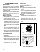
• The thermostat should be mounted about 5 feet
above the floor on an inside wall. DO NOT install the
thermostat on an outside wall or any other location
where its operation may be adversely affected by radiant
heat from fireplaces, sunlight, or lighting fixtures, and
convective heat from warm air registers or electrical
appliances. Refer to the thermostat manufacturer’s
instruction sheet for detailed mounting and installation
information.
START UP & ADJUSTMENTS
Pre-Start Check List
√ Verify the indoor unit is level and allows proper
condensate drainage.
√ Verify the outdoor coil and top of the unit are free from
obstructions and debris, and all equipment access/
control panels are in place.
√ Verify air filters are cleaned and properly installed.
√ Verify duct work is sealed to prevent air leakage.
√ Verify line voltage power leads are securely connected
and the unit is properly grounded.
√ Verify low voltage wires are securely connected to the
correct leads on the low voltage terminal strip.
√ Verify power supply branch circuit overcurrent protection
is sized properly.
√ Verify the thermostat is wired correctly.
Start-Up Procedures
The thermostat's function mode should be set to OFF and
the fan mode should be set to AUTO. Close all electrical
disconnects to energize the system.
Air Circulation - Indoor Blower
1. Set the thermostat system mode on OFF and the fan
mode to ON.
2. Verify the blower runs continuously. Check the air
delivery at the supply registers and adjust register
openings for balanced air distribution. If insufficient air
is detected, examine ductwork for leaks or obstructions.
3. Set the thermostat fan mode to AUTO and verify the
blower stops running.