SERVICE MANUAL Inverter Flex Multi-Zone Ductless Mini Split Outdoor Section A-VMH18DC-1 A-VMH27TC-1 A-VMH36QC-1 Heat Controller, Inc. • 1900 Wellworth Ave. • Jackson, MI 49203 • (517)787-2100 • www.heatcontroller.
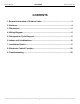
Service Manual VMH Series Heat Controller, Inc. CONTENTS 1.General Information of Outdoor Units............................................................ 3 2. Features........................................................................................................... 4 3. Dimensions...................................................................................................... 5 4. Wiring Diagram...............................................................................................
VMH Series Heat Controller, Inc. Service Manual 1. General information of Outdoor Units Model name Dimension mm(in) Compressor A-VMH18DC-1 845x320x700(33.3x12.6x27.6) DA130S1C-20FZ A-VMH27TC-1 845x320x700(33.3x12.6x27.6) DA150S1C-20FZ A-VMH36QC-1 990x345x965(39x13.
Service Manual VMH Series Heat Controller, Inc. 2.Features Outdoor unit Power relay control Low noise air flow system Hydrophilic aluminum fin The hydrophilic fin is corrosion resistant and improves heating efficiency in heat mode by absorbing the water on its surface and by spreading the water instead of forming water droplets. 4 way valve control Operates only in heating mode except during defrosting.
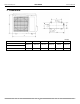
VMH Series Heat Controller, Inc. Service Manual 3. Dimensions mm(in) Model A-VMH18DC-1 A-VMH24TC-1 A-VMH36QC-1 W D H W1 A B 845((33.3) 320(12.6) 700(27.6) 908(35.7) 560(22) 335(13.2) 990(39) 345(13.6) 965(38) 1075(42.3) 624(24.6) 366(14.
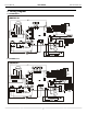
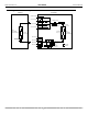
Service Manual VMH Series 4. Wiring Diagram 4.1 A-VMH18DC-1 4.2 A-VMH27TC-1 6 Heat Controller, Inc.
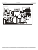
Heat Controller, Inc. VMH Series 4.
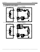
VMH Series Service Manual Heat Controller, Inc. 5. Refrigeration Cycle Diagram 8.1 Refrigeration circuit drawing of inverter dual zone: A-VMH18DC-1 INDOOR OUTDOOR LIQUID VALVE A LIQUID VALVE B EXV A CAPILIARY A CHECK VALVE EXV B CAPILIARY B CAPILIARY TUBE HEAT EXCHANGE (EVAPORATOR) T4 Ambient temp. sensor T1 Room temp. sensor T2 Evaporator temp. sensor T3 Condenser temp. sensor HEAT EXCHANGE (CONDENSER) GAS VALVE A 4-WAY VALVE GAS VALVE B Accumulator T5 Discharge temp. sensor Compressor 5.
VMH Series Heat Controller, Inc. Service Manual 8.3 Refrigeration circuit drawing of inverter Quad-zone: A-VMH36QC-1 INDOOR OUTDOOR LIQUID VALVE A LIQUID VALVE B EXV A CAPILIARY A EXV B CAPILIARY B CHECK VALVE LIQUID VALVE C LIQUID VALVE D HEAT EXCHANGE (EVAPORATOR) EXV C CAPILIARY C EXV D CAPILIARY D CAPILIARY TUBE T4 Ambient temp. sensor T1 Room temp. sensor T3 Condenser temp. sensor HEAT EXCHANGE (CONDENSER) GAS VALVE A T2 Evaporator temp.
VMH Series Service Manual 6. Indoor units combination Heat Controller, Inc. NOTE: The total capacity of indoor air handlers can not exceed the nominal capacity of the outdoor unit. The minimum quantity of indoor air handlers is one on any outdoor unit, whether it is a dual, tri, or quad zone. 6.1 Indoor unit combinations for A-VMH18DC-1 Comb. Dual(1x1) Dual (1x2) Combinations Unit A Unit B 9k — 12k — 18k — 9k 9k 9k 12k 6.2 Indoor unit combinations A-VMH27TC-1 Comb.
VMH Series Heat Controller, Inc. Service Manual 7. Installation Details 7.1 Wrench torque sheet for installation Outside diameter Torque Additional tightening torque N.m 16(163kgf.cm) mm inch Ф6.35 1/4 N.m 15(153kgf.cm) Ф9.52 3/8 25(255kgf.cm) 26(265kgf.cm) Ф12.7 1/2 35(357kgf.cm) 36(367kgf.cm) 7.2 Connecting the cables The power wiring should always follow NEC and local codes, with respect to the unit’s, rating plate. See installation manual for additional information.
VMH Series Service Manual Heat Controller, Inc. 7.4 Installation for the first time Air and moisture in the refrigerant system have undesirable effects as indicated below: ● ● ● ● ● Pressure in the system rises. Operating current rises. Cooling or heating efficiency drops. Moisture in the refrigerant circuit may freeze and block capillary tubing. Water may lead to corrosion of parts in the refrigerant system.
Heat Controller, Inc. VMH Series Service Manual the pressure can’t achieve -0.1Mpa after pumping 50 minutes, please check if there are some leakage points. Once the meter indicates -0.1mpa, fully close the handle Lo valve of the manifold valve and stop the operation of the vacuum pump. Confirm that the gauge needle does not move (approximately 5 minutes after turning off the vacuum pump).
VMH Series Service Manual Heat Controller, Inc. 7). Replace the valve stems nuts and the service port cap that were previously removed. Be sure to use a torque wrench to tighten the service port cap to a torque of 18N·m. Be sure to check for gas leakage using soap water. 3. Adding the refrigerant if the pipe length >(5m)16.5ft Electronic scale Procedure: 1). Connect the charge hose to the charging cylinder, open the 2-way valve and the 3-way valve.
Heat Controller, Inc. VMH Series Service Manual 6).When the electronic scale displays the proper weight (refer to the table), disconnect the charge hose from the 3-way valve’s service port immediately and turn off the air conditioner before disconnecting the hose. 7). Replace the valve stem caps and the service port that were previously removed. Use torque wrench to tighten the service port cap to a torque of 18N.m. Be sure to check for gas leakage using soap water. 7.
Service Manual VMH Series Heat Controller, Inc. side), disconnect the charge hose from the 3-way valve’s service port immediately and turn off the air conditioner before disconnecting the hose. 7). Replace the valve stem caps and the service port that were previously removed. Use torque wrench to tighten the service port cap to a torque of 18N.m. Be sure to check for gas leakage using soap water. 7.6 Replacing the indoor unit 1. Collecting the refrigerant into the outdoor unit Procedure 1).
Heat Controller, Inc. VMH Series Service Manual Do this quickly so that the gauge ends up indicating 0.3 to 0.5Mpa. Disconnect the charge set, and tighten the 2-way and 3-way valve’s stem nuts. Use a torque wrench to tighten the 3-way valves service port cap to a torque of 1.8 N.m. Be sure to check for gas leakage using soap water. 7). Remove the defective indoor unit and install the new indoor unit. Follow the next set of procedures to charge. 2. Air purging by the refrigerant Procedure: 1).
Service Manual VMH Series Heat Controller, Inc. 2-way valve approximately 45° until the gauge indicates 0.3 to 0.5 Mpa. 6). Disconnect the charge set and the charging cylinder, and set the 2-way and 3-way valves to the open position Be sure to use a hexagonal wrench to operate the valve stems. 7). Replace the valve stems nuts and the service port cap that were previously removed. Be sure to use a torque wrench to tighten the service port cap to a torque 18N.m.
Heat Controller, Inc. VMH Series Service Manual 2. Refrigerant charging Procedure: 1). Connect the charge hose to the charging cylinder, open the 2-way valve and the 3-way valve Connect the charge hose which you disconnected from the vacuum pump to the valve at the bottom of the cylinder. Because the refrigerant is R-410A, turn the cylinder upside down, such that the bottom is upward, to ensure a liquid charge. 2).
VMH Series Service Manual Heat Controller, Inc. 8. Electronic control function 8.1 Abbreviations T1: Indoor ambient temperature T2: Coil temperature of indoor heat exchanger middle. T2B: Coil temperature of indoor heat exchanger outlet. T3: Coil temperature of outdoor heat exchanger T4: Outdoor ambient temperature T5: Compressor discharge temperature Ts: Set point temperature. 8.2 Electric control working environment. 8.2.1 Input voltage: 230V. 8.2.2 Input power frequency:60Hz. 8.2.
VMH Series Heat Controller, Inc. discharge temp. is 105 degree. If the indoor unit is not connected, the digital display tube will show: “- - “. AD data 12 Inverter current 13 EXV open angle for 1# indoor unit 14 EXV open angle for 2# indoor unit 15 EXV open angle for 3# indoor unit 16 EXV open angle for 4# indoor unit 17 Power supply of outdoor unit Indoor unit number The last error or protection code 18 19 Service Manual 20 frequency value 21 Ambient temp. of 22 Condenser pipe temp.
VMH Series Service Manual Heat Controller, Inc. 8.4.4Number of indoor units – displays how many indoor units the outdoor unit is communicating with. Display Quantity of indoor unit 1 1 2 2 3 3 4 4 8.4.5 Opening degree of electronic expansion valve: Actual opening degree value equals the display data divided 8 8.5 Protection 8.5.1 Three minutes delay at restart for compressor. 8.5.2 Temperature protection of compressor discharge. When the compressor discharge temp.
VMH Series Heat Controller, Inc. Service Manual 8.5.4 Compressor current limit protection If the compressor current exceeds the current limit value for 10 seconds, the compressor frequency will be limited per the table below.
Service Manual VMH Series Heat Controller, Inc. 8.5.5 Indoor / outdoor units communication protection If any indoor unit can not receive the feedback signal from the outdoor unit for 2 minutes, the AC will stop and display the failure code. 8.5.6 High condenser coil temp. protection. When T3>149°F(T3>65°C) for 3 seconds, the compressor will stop while the indoor fan and outdoor fan will continue. When T3<126°F(T3<52°C), the protection will release and the compressor will restart after 3 minutes. 8.5.
VMH Series Heat Controller, Inc. Service Manual 9. Troubleshooting 9.
VMH Series Service Manual Heat Controller, Inc. 9.2 Outdoor unit error code explanation: Outdoor Error Corresponding Indoor LED STATUS Mini-Split error code Code: E0 E1 E2 E3 E6 Outdoor EEPROM malfunction E5 Indoor unit A’s coil outlet temp. sensor or connector of sensor is defective Indoor unit B’s coil outlet temp. sensor or connector of sensor is defective Indoor unit C’s coil outlet temp. sensor or connector of sensor is defective Indoor unit D’s coil outlet temp.
VMH Series Heat Controller, Inc. Service Manual 9.3 Trouble shooting 9.3.1 Indoor unit trouble shooting 9.3.1.1 Indoor EEPROM malfunction Shut off the power supply and turn it on 1 minute later. Is it still displaying the error code? Yes If the EEPROM chip is welded on PCB, replace the PCB directly. Otherwise, check whether the EEPROM chip plugged in PCB well? No Insert the EEPROM well Re-insert the EEPROM well Yes Replace the indoor PCB.
VMH Series Service Manual Heat Controller, Inc. 9.3.1.2 Indoor / outdoor units communication error Yes Power off , then Power on the A/C by the Breaker. Did E1 error code turn off? No No Check wiring on the outdoor and indoor terminal follow the wiring diagram.
Heat Controller, Inc. VMH Series Service Manual Pic 1: Measure the voltage of L2 to S (Vs), is it moving alternately between positive value and negative value? PIC 2, Check the wiring. PIC 3: IPM (For dual/tri/quad-zone) PFC (quad-zone only) PIC4: Main board LED when power on and unit standby. PIC 5: check point bottom, press 18 times to check how many indoor units are connected.
VMH Series Service Manual 9.3.1.3 Zero-crossing signal error Check if the connections and are normal? power supply is normal? Heat Controller, Inc. Correct the connections. Turn on the unit Correct the connections. Turn on the when the power supply is within 90-110% of unit when the power supply is good. No rated voltage on unit’s rating plate. Yes Indoor PCB is defective. Replace indoor PCB. 9.3.1.
VMH Series Heat Controller, Inc. Service Manual 9.3.1.5 Indoor fan speed has been out of control(AC fan motor) Shut off the power supply and turn it on 5 seconds later.Is it still displaying the error code? No The unit operates normally. Yes Shut off the power supply, rotate the cross fan by hand. Does it rotate properly? freely? No Disassembly the connection between fan and motor, check if the bearing is normal? No Yes Yes Check the wires of fan motor.
VMH Series Service Manual Heat Controller, Inc. 9.3.1.6 Open or short circuit of temperature sensor. Check the connections between temperature sensor and PCB. Are the connections good? No Correct the Correct theconnections. connections per wiring diagram. Yes Replace indoor or outdoor PCB. Yes Check the resistance value of the sensor via Appendix 1, is it normal? No Replace sensor and Replace the the sensor check if the problem happen again? 9.3.1.
VMH Series Heat Controller, Inc. Service Manual 9.3.1.8 Outdoor temp. too low protection(Optional for some models) Check if the outdoor ambient temperature is beyond the normal operation temperature range. Yes Turn on the unit when outdoor ambient temperature is in normal operation temperature range. No Replace the outdoor ambient temperature sensor. 9.3.2 Outdoor unit trouble shooting 9.3.
VMH Series Service Manual Heat Controller, Inc. 9.3.2.
VMH Series Heat Controller, Inc. Service Manual 9.3.2.3 Communication malfunction between IPM board and outdoor main board(ODU E7) Communication malfunction between IPM board and outdoor main board Is there at least one LED in lit? the IPM board light? No Check the signal wire between the IPM module and the main board, is it connected good? No Yes Yes Reconnect and retry.
VMH Series Service Manual Heat Controller, Inc. 9.3.2.4 Temperature protection of compressor discharge (ODU P0) Temperature protection of compressor discharge Check whether the compressor discharge temp. is more than 239°F (115°C)? Check whether there is a refrigerant leak Yes Yes Stop leak and add refrigerant as needed No Check whether the wiring connection is correct between compressor discharge temp.
VMH Series Heat Controller, Inc. Service Manual 9.3.2.5 Temperature protection of compressor top (ODU P0) Temperature protection of compressor top Does the compressor operate? No Are all connections correct? Yes No Reconnect and retest.
VMH Series Service Manual Heat Controller, Inc. 9.3.2.
VMH Series Heat Controller, Inc. 9.3.2.
VMH Series Service Manual Heat Controller, Inc. 9.3.2.8 Current protection of compressor (ODU P3) Current protection of compressor Check whether the input current of the power supply wire is more than 12.5A (For 27K, it is 14.5A, For 36K, it is 20A) Yes Check whether the refrigerant system is ok Check whether the outdoor ambient temperature is higher than 122.
VMH Series Heat Controller, Inc. Service Manual 9.3.2.
VMH Series Service Manual Heat Controller, Inc. 9.3.2.10 High temperature protection of condenser (ODU P6) When outdoor pipe temp. is mroe than 149°F (65°C), the unit will stop, and will run again when outdoor pipe temp. is less than 126°F (52°C).
VMH Series Heat Controller, Inc. 9.3.2.
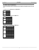
VMH Series Service Manual Heat Controller, Inc. Appendix 1 Temperature Sensor Resistance Value Table (℃--K) Use appendix 4 to convert °C to °F. ℃ K Ohm ℃ K Ohm ℃ K Ohm ℃ K Ohm -20 115.266 20 12.6431 60 2.35774 100 0.62973 -19 108.146 21 12.0561 61 2.27249 101 0.61148 -18 101.517 22 11.5000 62 2.19073 102 0.59386 -17 96.3423 23 10.9731 63 2.11241 103 0.57683 -16 89.5865 24 10.4736 64 2.03732 104 0.56038 -15 84.2190 25 10.000 65 1.96532 105 0.
VMH Series Heat Controller, Inc. Service Manual Appendix 2 Unit: °C ---K Discharge temp. sensor table -20 542.7 20 68.66 60 13.59 100 3.702 -19 511.9 21 65.62 61 13.11 101 3.595 -18 483 22 62.73 62 12.65 102 3.492 -17 455.9 23 59.98 63 12.21 103 3.392 -16 430.5 24 57.37 64 11.79 104 3.296 -15 406.7 25 54.89 65 11.38 105 3.203 -14 384.3 26 52.53 66 10.99 106 3.113 -13 363.3 27 50.28 67 10.61 107 3.025 -12 343.6 28 48.14 68 10.
VMH Series Service Manual Heat Controller, Inc. Appendix 3 1. Reference voltage data: a) Rectifier : Input :220-230V(AC), output :310V(DC) b) Inverter module: U,V, W 3ph. Result U-V 60-150V(AC) U-W 60-150V(AC) V-W 60-150V(AC) P-N DC 310V 2. Check the Diode Bridge component ( In wiring diagram, rectifier) Remark: If this part is abnormal, the LED will not light. ~ + - ~ Multi-meter + ~ ~ - Result _ + ~ ~ Forward Resistance Backward Resistance Infinite Infinite ~1.
Heat Controller, Inc.
VMH Series Service Manual Heat Controller, Inc. Appendix 5: Spec. Outdoor unit Model 1x2 1x3 1x4 Compressor DA130S1C-20FZ DA150S1C-20FZ TNB306FPGMC-L Outdoor fan motor YDK70-6FB YDK70-6FB YDK180-8GB Indoor unit Model 9k Mini-Split 12k Mini-Split 18k Mini-Split Indoor fan motor RPG20B RPG20B RPG28H Model / 12k Cassette 18k Cassette Indoor fan motor / YDK45-6B YDK45-6B 1. Compressor checking Measure the resistance value of each winding by using the tester.
VMH Series Heat Controller, Inc. 2. Service Manual Fan Motor. Measure the resistance value of each winding by using the tester. Position Resistance Value YDK70-6FB YDK180-8GB YSK27-4G YSK68-4B YDK45-6B YSK25-6L Black - Red 56Ω±8% (20℃) 24.5Ω±8% (20℃) 317Ω±8% (20℃) 145Ω±8% (20℃) 345Ω±8% (20℃) 627Ω±8% (20℃) Red - Yellow 76Ω±8% (20℃) 19Ω±8% (20℃) 252Ω±8% (20℃) 88Ω±8% (20℃) 150Ω±8% (20℃) 374.
10-2012 04/2009