HEAT CONTROLLER, INC. Wall Mounted Multi-Zone Split System Air Conditioning/Heat Pump Indoor Unit: B-MMC09FA-1 B-MMH09FA-1 B-MMC12FA-1 B-MMH12FA-1 Outdoor Unit : A-MMC18FA-1 A-MMH18FA-1 A-MMC24FA-1 A-MMH24FA-1 A-MMC36FA-1 A-MMH36FA-1 Before servicing the unit, read the “safety precautions” in this manual. Only for authorized service personnel.
Wall Mounted Multi-Zone Split System Air Conditioner Service Manual TABLE OF CONTENTS Combination table.......................................................................................................................................3 Safety Precautions......................................................................................................................................4 Seaside applications and installation ...............................................................................
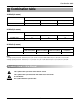
Combination table Combination table 18 kBtu/h( 2 rooms) Combination Indoor Unit A(kBtu/h) Indoor Unit B(kBtu/h) Total(kBtu/h) 9 9 18 2 Indoor Units 24 kBtu/h( 2 rooms) Combination Indoor Unit A(kBtu/h) Indoor Unit B(kBtu/h) Total(kBtu/h) 12 12 24 2 Indoor Units 36 kBtu/h (3 rooms) Combination 3 Indoor Units Indoor Unit A(kBtu/h) Indoor Unit B(kBtu/h) Indoor Unit C(kBtu/h) Total(kBtu/h) 12 12 12 36 Notes : 1.Cooling Capacity is based on : indoor temp. 26.7°C(80.1°F)DB, 19.4°C(66.
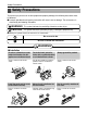
Safety Precautions Safety Precautions To prevent injury to the user or other people and property damage, the following instructions must be followed. ■ Incorrect operation due to ignoring instruction will cause harm or damage. The seriousness is classified by the following indications. WARNING This symbol indicates the possibility of death or serious injury. CAUTION This symbol indicates the possibility of injury or damage to properties only.
Safety Precautions Do not install, remove, or reinstall the unit by yourself (customer). • There is risk of fire, electric shock, explosion, or injury. Do not install the product on a defective installation stand. • It may cause injury, accident, or damage to the product. Do not allow water to run into electric parts. • It may cause There is risk of fire, failure of the product, or electric shock. Be cautious when unpacking and installing the product. • Sharp edges could cause injury.
Safety Precautions When flammable gas leaks, turn off the gas and open a window for ventilation before turn the product on. If strange sounds or smoke come from the product, turn the breaker off. Stop operation and close the window in storm or hurricane. If possible, remove the product from the window before the hurricane arrives. • Do not use the telephone or turn switches on or off. There is risk of explosion or fire • There is risk of electric shock or fire.
Safety Precautions When the product is not being used for a long time, disconnect the power by turning off the breaker. Take care to ensure that nobody could step on or fall onto the outdoor unit. • There is risk of product damage or failure, or unintend- • This could result in personal injury and product damed operation. age. CAUTION ■ Installation Always check for gas (refrigerant) leakage after installation or repair of product. • Low refrigerant levels may cause failure of product.
Safety Precautions ■ Operational Do not expose the skin directly to cool air for long periods of time. (Don't sit in the draft.) • This could harm to your health. Use a soft cloth to clean. Do not use harsh detergents, solvents, etc. • There is risk of fire, electric shock, or damage to the plastic parts of the product. Do not use the product for special purposes, such as preserving foods, works of art, etc. It is a consumer air conditioner, not a precision refrigeration system.
Safety Precautions Use a firm stool or ladder when cleaning or maintaining the product. Replace the all batteries in the remote control with new ones of the same type. Do not mix old and new batteries or different types of batteries. • Be careful and avoid personal injury. • There is risk of fire or explosion Do not recharge or disassemble the batteries. Do not dispose of batteries in a fire. If the liquid from the batteries gets onto your skin or clothes, wash it well with clean water.
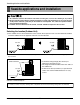
Seaside applications and installation Seaside applications and installation 1. Air conditioners should not be installed in areas where corrosive gases, such as acid or alkaline gas, are produced. 2. Do not install the product where it could be exposed to sea wind (salty wind) directly. It can result corrosion on the product. Corrosion, particularly on the condenser and evaporator fins, could cause product malfunction or inefficient performance. 3.
Dimensions Dimensions Indoor Unit Split Type Indoor H D W Installation plate Model Split Type 9 kBtu/h Dimension 12 kBtu/h W mm(in) 840(33) 895(35.2) H mm(in) 270(10.6) 282(11.1) D mm(in) 153(6) 165(6.
Dimensions Outdoor Unit L4 L1 H L3 L2 D W L6 L5 L7 UE 18kBtu/h MODEL DIM W mm(in) 870(34.3) H mm(in) 655(25.8) D mm(in) 320(12.6) L1 mm(in) 370(14.6) L2 mm(in) 25(1.0) L3 mm(in) 775(30.5) L4 mm(in) 25(1.0) L5 mm(in) 546(21.5) L6 mm(in) 160(6.3) L7 mm(in) 160(6.
Dimensions L4 L1 H L3 L2 D W L6 L5 L7 UE 1 24kBtu/h MODEL DIM W mm(in) 870(34.3) H mm(in) 808(31.8) D mm(in) 320(12.6) L1 mm(in) 370(14.6) L2 mm(in) 25(1.0) L3 mm(in) 775(30.5) L4 mm(in) 25(1.0) L5 mm(in) 546(21.5) L6 mm(in) 160(6.3) L7 mm(in) 160(6.
Dimensions L5 L1 L10 L11 L11 L11 L11 L11 L4 H L3 D L2 W Gas side 3-way valve Liquid side 2-way valve L9 L7 L6 L8 UE2 36kBtu/h MODEL DIM W mm(in) 870(34.3) H mm(in) 1038(40.7) D mm(in) 320(12.6) L1 mm(in) 360(14.2) L2 mm(in) 340(13.4) L3 mm(in) 25(1.0) L4 mm(in) 1035(40.8) L5 mm(in) 25(1.0) L6 mm(in) 546(21.5) L7 mm(in) 160(6.3) L8 mm(in) 160(6.3) L9 mm(in) 44(11.7) L10 mm(in) 64.5(2.5) L11 mm(in) 50(2.
Product Specifications Product Specifications Indoor Unit Indoor Unit Type Model Wall Mounted kcal/h(W) B-MMC09FA-1 2,267(2,637) B-MMH09FA-1 2,267(2,637) B-MMC12FA-1 3,023(3,516) B-MMH12FA-1 3,023(3,516) Btu/h 9,000 9,000 12,000 12,000 kcal/h(W) - 2,267(2,637) - 3,023(3,516) Btu/h - 9,000 - 12,000 CFM(CMM) 289(8.2) 289(8.2) 332(9.4) 332(9.
Product Specifications Outdoor Unit - Multiple piping models Model Cooling Capacity Heating Capacity Input Running Current(208/230V) Cooling Heating Cooling Heating A-MMC18FA-1 Btu/hr W kcal/hr Btu/hr W kcal/hr W W A A Ø,V,Hz Power Supply Max. Number of Connectable Indoor Units Compressor Type (Constant) Model Motor Type Quantity Ea Motor Input W Oil Charge cc Oil Type Capacitor µF/Vac O.L.
Product Specifications Model Cooling Capacity Heating Capacity Input Running Current(208/230V) Cooling Heating Cooling Heating Btu/hr W kcal/hr Btu/hr W kcal/hr W W A A Ø,V,Hz Power Supply Max. Number of Connectable Indoor Units Compressor Type (Constant) Model Motor Type Quantity Ea Motor Input W Oil Charge cc Oil Type Capacitor µF/Vac O.L.P Type(model name) Compressor Type (Constant) Model Motor Type Quantity Ea Motor Input W Oil Charge cc Oil Type Capacitor µF/Vac O.L.
Product Specifications Model Cooling Capacity Heating Capacity Input Running Current(208/230V) Cooling Heating Cooling Heating Btu/hr W kcal/hr Btu/hr W kcal/hr W W A A Ø,V,Hz Power Supply Max. Number of Connectable Indoor Units Compressor Type (Constant) Model Motor Type Quantity Ea Motor Input W Oil Charge cc Oil Type Capacitor µF/Vac O.L.P Type(model name) Compressor Type (Constant) Model Motor Type Quantity Ea Motor Input W Oil Charge cc Oil Type Capacitor µF/Vac O.L.
Installation Installation Read carefully and then follow step-by-step.
Installation Selecting the best location Indoor unit 1. Do not have any heat or steam near the unit. More than 10 cm (3.9 inch) 2. Select a place where there are no obstacles in front of the unit. 3. Make sure that condensation drainage can be conveniently routed away. More than 20 cm (7.9 inch) 4. Do not install near a doorway. 5. Ensure the unit is unobstructed, allow proper space on all sides according to the arrows and distance measurements in the figures. More than 2.4m (8 ft) More than 10 cm (3.
Installation Piping length and elevation Multi Piping Type Max Elevation Max elevation between each between indoor indoor unit and units (h2) outdoor unit (h1) 7.5 m (25 ft) 7.5 m (25 ft) Capacity Max total length of all pipes (A+B/A+B+C) Max length of each pipe (A/B/C) Min length of each pipe (A/B/C) 18 kBtu 30 m (100 ft) 15 m (50 ft) 3 m (10 ft) 24 kBtu 30 m (100 ft) 15 m (50 ft) 3 m (10 ft) 7.5 m (25 ft) 7.5 m (25 ft) 36 kBtu 45 m (150 ft) 15 m (50 ft) 3 m (10 ft) 7.5 m (25 ft) 7.
Installation Installing Installation Plate(Standard Type) The wall you select should be strong and solid enough to prevent vibration Installation Plate 1. Mount the installation plate on the wall with type "A" screws. If mounting the unit on a concrete wall, use anchor bolts. • Mount the installation plate horizontally by aligning the centerline using a level. Chassis Hook Type "A" screw 2. Measure the wall and mark the centerline.
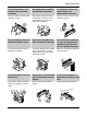
Flaring Work and Connection of Piping Flaring Work and Connection of Piping Flaring work The main cause for gas leakage is due to defects in flaring work. Carry out correct flaring work using the following procedures. Cut the pipes 1. Use the copper pipe purchased locally. 2. Measure the distance between the indoor and the outdoor unit. Copper pipe 3. Cut the pipes a little longer than measured distance. Slanted Uneven Rough 90° 4. Cut the cable 1.5m (5.0ft) longer than the pipe length.
Flaring Work and Connection of Piping Check 1. Compare the flare work like the figure on the right. Smooth all around Inside is shiny without scratches 2. If a flared section is defective, cut it off and repeat the flaring process again. = Improper flaring = Even length all around Inclined Surface Cracked Uneven damaged thickness Connecting the Piping Indoor 1. Prepare the indoor unit's piping and drain hose for installation through the wall. 2.
Flaring Work and Connection of Piping 4. Indoor unit installation Hook the indoor unit onto the upper portion of the installation plate.(Engage the two hooks of the rear top of the indoor unit with the upper edge of the installation plate.) Ensure that the hooks are properly seated on the installation plate by moving the indoor unit left and right.
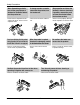
Flaring Work and Connection of Piping For left rear piping 1. Route the indoor tubing and the drain hose to the required piping hole position. 2. Insert the piping, drain hose, and the connecting cable into the piping hole. Connecting cable 3. Insert the connecting cable into the indoor unit. • Don't connect the cable to the indoor unit. • Make a small loop with the cable for easy connection later. Drain pipe 4. Tape the drain hose and the connecting cables. 5.
Flaring Work and Connection of Piping Wrap the insulation material around the connecting portion. 1. Overlap the connection pipe insulation and the indoor unit pipe heat insulation material. Bind them together with vinyl tape so that there is no gap. Plastic bands Insulation material 2. Wrap the area which accommodates the rear piping housing section with vinyl tape. Indoor unit piping Connection pipe Vinyl tape (wide) Wrap with vinyl tape Pipe Vinyl tape(narrow) Connecting cable 3.
Flaring Work and Connection of Piping Installation Information. For left piping. Follow the instruction below. Good case • Press on the upper side of clamp and unfold the tubing to slowly downward. Bad case • Bending the pipe from right to left may cause damage to the tubing.
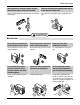
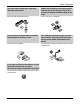
Flaring Work and Connection of Piping REMOTE CONTROL PREPARATION(OPTIONAL) HOW TO MOUNT ONTO A WALL HOW TO INSERT BATTERIES Remove the battery cover from the remote controller. • Slide the cover according to the arrow direction. Insert the two batteries.(AAA, 1.5V) • Be sure that the (+) and (-) directions are correct. • Be sure that both batteries are new. Re-attach the cover. • Slide it back into position.
Flaring Work and Connection of Piping Outdoor Align the center of the piping and sufficiently tighten the flare nut by hand. Finally, tighten the flare nut with torque wrench until the wrench clicks. • When tightening the flare nut with torque wrench, ensure the direction for tightening follows the arrow on the wrench. Outside diameter mm inch Ø6.35 1/4 Ø9.52 3/8 Outdoor unit 18/24 kBtu/h Torque kg.m 1.8 4.2 A-UNIT Gas side piping lbf.in 156.2 364.
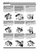
Connecting the Cable between Indoor Unit and Outdoor Unit Connecting the Cable between Indoor Unit and Outdoor Unit Connect the cable to the Indoor unit. Connect the cable to the indoor unit by connecting the wires to the terminals on the control board individually according to the outdoor unit connection. (Ensure that the color of the wires of the outdoor unit and the terminal No. are the same as those of the indoor unit.) The ground wire should be longer than the common wires.
Connecting the Cable between Indoor Unit and Outdoor Unit Connect the cable to the Outdoor unit. 1. Remove the control cover from the unit by loosening the screw. Connect the wires to the terminals on the control board individually as the following. Outdoor unit Terminal block Over 5mm (0.2inch) Holder for power supply cord 2. Secure the cable onto the control board with the holder (clamper). 3. Re-attach the control cover to the original position using the screws.
Connecting the Cable between Indoor Unit and Outdoor Unit Methods of connecting the cable (1) Remove two-caps on the conduit panel. (for low voltage line) (2) Pull out connection cable through conduit. (3) After conduit to the panel, fix nut to the opposite side of panel. Terminal block (4) Pass the connection cable through the hole. (5) Properly connect the cable on the terminal block.
Connecting the Cable between Indoor Unit and Outdoor Unit CAUTION: Provide a circuit breaker between power source and the unit as shown below. Main power source Model Air Conditioner Circuit Breaker Use a circuit breaker or time delay fuse. 18 kBtu/h 24 kBtu/h 36 kBtu/h Power source Fuse or breaker Capacity 1Ø, 230 / 208V 1Ø, 230 / 208V 1Ø, 230 / 208V Connect the cable to the indoor unit 1. Connect the wires to the terminals on the control board individually according to the outdoor unit connection.
Checking the Drainage, Insulating the Pipe and Special Piping Applications Checking the Drainage, Insulating the Pipe and Special Piping Applications Checking the drainage To check the drainage. 1. Pour a glass of water on the evaporator. 2. Ensure the water flows through the drain hose of the indoor unit without any leakage and goes out the drain exit. Drain piping 1. The drain hose should point downward for easy drain flow. Downward slope 2.
Checking the Drainage, Insulating the Pipe and Special Piping Applications Insulating the Pipe and Special Piping Applications Insulate the piping by wrapping the connecting portion of the indoor unit with insulation material and secure it with two layers of vinyl tape. Seal any small opening around the piping with gum type sealant. Taping • If you want to connect an additional drain hose, the end of the drain outlet should be routed above the ground. Secure the drain hose appropriately.
Air Purging and Evacuation Air Purging and Evacuation Air and moisture remaining in the refrigerant system have undesirable effects as indicated below. 1. Pressure in the system rises. 2. Operating current rises. 3. Cooling(or heating) efficiency drops. 4. Moisture in the refrigerant circuit may freeze and block capillary tubing. 5. Water may lead to corrosion of parts in the refrigeration system.
Air Purging and Evacuation Evacuation 1. Connect the charge hose end described in the preceding steps to the vacuum pump to evacuate the tubing and indoor unit. Confirm the "Lo" knob of the manifold valve is open. Then, run the vacuum pump. The operation time for evacuation varies with tubing length and capacity of the pump. The following table shows the time required for evacuation. Outdoor unit Required time for evacuation when 4 CFM vacuum pump is used If tubing length is less than 10m (33 ft) 10 min.
Charging Charging ■ Each outdoor unit is factory charged (see rating plate) for the evaporator as well as a 7.5m(25ft) line set for each indoor line. Any time the total line set is used either shorter or longer then the nominal line set length the refrigerant charge has to be adjusted. ■ Whether the line set is made shorter or longer you must adjust the charge based on how many m(ft) of tubing are either added or removed based on 20g(0.22oz) of R-410A per meter(foot).
Test Running Test Running Split Type 1. Check that all copper piping and wiring has been properly connected. 2. Check that the gas and liquid side service valves are fully open. 1) Prepare remote controller Remove the battery cover by pulling it according to the arrow direction. Insert new batteries making sure that the (+) and (–) of battery are installed correctly. Reattach the cover by pushing it back into position. Bolt Tubing connection 4) Evaluation of the performance NOTE: • Use 2 AAA(1.
Operation Operation Function of control 1. MAIN UNIT FUNCTION • DISPLAY Operation Indicator • On while in appliance operation, off while in appliance pause • Flashing if unit is disconnected or has experienced a short in the thermistor (3 seconds off/0.5 sec on). Sleep Timer Indicator • On while in sleep time mode, off when sleep timer mode is canceled or appliance operation is paused.
Operation operates (except in sleep mode, the airflow will be at medium speed). • While compressor is off, the indoor fan is off when the indoor pipe temp is below 33°C(91.4°F), when above 35°C(95°F) , it operates with the low airflow speed. • While in defrost mode, the indoor and outdoor fans are turned off. ■ Defrost Control(Heating) • While in defrost mode, the indoor and outdoor fans are turned off. • Defrost operation is controlled by timer and sensing temperature of the outdoor pipe.
Operation 2) Fuzzy Operation for Dehumidification • According to the set point temperature selected by Fuzzy rule, when the intake air temp is 0.5°C(0.9°F) or more below the set point temp, the compressor is turned off. When 0.5°C(0.9°F) or more above the set point temp, the compressor is turned on. Compressor ON Temp ➲ Set point Temp + 0.5°C(0.9°F) Compressor OFF Temp ➲ Set point Temp+0.5°C(0.
Operation • If the appliance is paused at the time set by the timer, the pause continues. ■ Off-Timer <=> On-Timer Operation • When the set time is reached after the on/off time is input by the remote control, the on/off-timer operation is carried out according to the set time. ■ Sleep Timer Operation • When the sleep time is reached after <1,2,3,4,5,6,7,0(cancel) hr> is input by the remote control while in appliance operation, the operation of the appliance stops.
Operation ■ Forced Operation • To operate the appliance by force (in case the remote control is lost), the forced operation selection switch is on the main unit of the appliance and operates it in standard conditions. • When the power is supplied while the slide switch is in the forced operation position, or the Auto Restart (or test operation) position or switched from the remote control position to the forced operation position while the power is on, the forced operation is carried out.
Operation Function of Indoor Unit Split Type Indoor Unit Operation ON/OFF by Remote controller Sensing the Room Temperature • Room temperature sensor. (THERMISTOR) Room temperature control • Maintains the room temperature in accordance with the set point Temp. Starting Current Control • Indoor fan is delayed for 5 seconds at the starting. Time Delay Safety Control • Restarting is delayed for approx. 3 minutes.
Operation Function of Outdoor Unit Outdoor Unit Operating Step • Compressor step varies considering conditions such as room temperature, operating room number, temperature gap between room temperature and set point temperature and so on. LEV Control • The linear expansion valve is pulse is modulated to keep constant superheat or subcooling. Outdoor Fan Control • Outdoor fan operates at High or Off to respond to the load condition.
Operation Remote Control Operation The Remote Controller transmits the signals to the system. Signal transmitter 1. START/STOP BUTTON Operation starts when this button is pressed and stops when the button is pressed again. 2. OPERATION MODE SELECTION BUTTON Used to select the operation mode. (Heat Pump) (Cooling Only) 3. ROOM TEMPERATURE SETTING BUTTONS Used to select the room temperature. 4. INDOOR FAN SPEED SELECTOR Used to select fan speed in four steps low, medium, high and CHAOS. 5 1 5.
Disassembly Disassembly Indoor Unit Split Type Indoor Unit Disconnect the unit from power supply before making any checks. Be sure the power switch is set to “OFF”. To remove the Grille from the Chassis. • Set the up-and-down air discharge louver to open position (horizontally) by finger pressure. • Remove the securing screws. • To remove the Grille, pull the lower left and right side of the grille toward you (slightly tilted) and lift it straight upward. 1.
Disassembly 2. To remove the Control Box. • Remove securing screws. • Pull the control box out from the chassis carefully. Screw 3. To remove the Discharge Grille. • Unhook the discharge grille and pull the discharge grille out from the chassis carefully. 4. To remove the Evaporator. • Remove 3 screws securing the evaporator(at the left 2EA in the Evaporator Holder, at the right 1EA). • Repairing the unit, do not damage the Caution label.
Disassembly • Unhook the tab on the right inside of the chassis at the same time, slightly pull the evaporator toward you until the tab is clear of the slot. 5. To remove the Motor Cover • Remove 2 securing screws. • Pull the motor cover out from the chassis carefully. Motor cover 6. To remove the Cross-Flow Fan • Loosen the screw securing the cross-flow fan to the fan motor (do not remove). • Lift up the right side of the cross-flow fan and the fan motor, separate the fan motor from the cross-flow fan.
Disassembly Schematic Diagram Electronic Control Device 1.
CN-JIG OUT_TH OUT_PIPE CN-TH2 SUCTION DISCHARGE CN-TH1 4 3 2 1 1 2 3 4 1 2 3 4 4 3 2 1 1 2 3 4 1 2 3 4 - 53 - 56K R04T 10K R01T DC 5V 1K R03T 1K R02T C01H-C04H : 103 R05H-R20H (R05H,R06H,R07H:6.2K 1%) (ETC: 12.1K 1%) DC 5V JIG_RX JIG_TX DC 5V IC01A 2 7036P 1 3 C02A 10 50V R03A,100 R02A,4.7K + R01B,1M JIG_TX JIG_RX PWM(C) PWM(B) PWM(A) OSC01B CST-8.00MGW C01A 0.
4.7K PWM(C) 4.7K PWM(B) 4.7K PWM(A) C24M 100uf C13M 100uf C01M 100uf R02M 9.1k 1% R15M 9.1k 1% + R27M 9.1k 1% R26M 10.2K 1% Q07M KRA101M + R14M 10.2K 1% Q04M KRA101M + R01M 10.2K 1% 6 7 6 7 6 7 21.5K 21.5K 5 4 2 3 2 C25M 102 100V 6.04K 1 2 3 2 C14M 102 100V 4.3K DC 5V 5 4 6.04K 1 2 3 2 C02M 102 100V 4.3K DC 5V 5 4 6.04K 1 21.5K 4.3K R03M 13K 1% 39.2K R16M 13K 1% 39.2K 1 51.1K 22 R28M 13K 1% 35.7K 20 1 51.1K 22 35.7K 20 1 51.1K 22 35.
Schematic Diagram Wiring Diagram 1. Indoor Unit 2.
Schematic Diagram 3) A-MMC24FA-1 4) A-MMH24FA-1 5) A-MMC36FA-1 6) A-MMH36FA-1 Wall Mounted Multi-Zone Split System Air Conditioner - 56 -
Schematic Diagram Component Locations 1. Indoor Unit MAIN P.C.B.
Schematic Diagram 2.
Schematic Diagram 3.
Schematic Diagram 2) Solder side Wall Mounted Multi-Zone Split System Air Conditioner - 60 -
Troubleshooting Guide Troubleshooting Guide Refrigeration Cycle Diagram 1. A-MMC18FA-1 OUTDOOR UNIT High pressure S/W Ø9.52 Room B Field Piping Gas Ø9.52 Room A Header Th3 Constant Compressor Th2 Constant Compressor Accumulator Th1 Heat Exchanger Field Piping Liquid Ø6.35 Room B EEV-B Ø6.35 Room A EEV-A Refrigerant Flow Cooling Strainer Th1: Discharge thermistor Th2: Discharge thermistor Th3: Outdoor temperature thermistor 2. A-MMH18FA-1 OUTDOOR UNIT Field Piping Gas Ø9.
Troubleshooting Guide 3. A-MMC24FA-1 OUTDOOR UNIT Field Piping Gas High pressure S/W Ø9.52 Room B Ø9.52 Room A Strainer Header Th3 Th2 Constant Compressor Constant Compressor Accumulator Th1 Heat Exchanger Field Piping Liquid Ø6.35 Room B EEV-B Ø6.35 Room A EEV-A Refrigerant Flow Cooling Strainer Th1: Discharge thermistor Th2: Discharge thermistor Th3: Outdoor temperature thermistor 4. A-MMH24FA-1 OUTDOOR UNIT Field Piping Gas Ø9.52 Room B Ø9.
Troubleshooting Guide 5. A-MMC36FA-1 OUTDOOR UNIT Ø9.52 Room C Field Piping Gas High pressure S/W Ø9.52 Room B Ø9.52 Room A Header Th3 Th2 Constant Compressor Constant Compressor Accumulator Th1 Heat Exchanger Field Piping Liquid Ø6.35 Room C EEV-C Ø6.35 Room B EEV-B Ø6.35 Room A EEV-A Refrigerant Flow Cooling Th1: Discharge thermistor Th2: Discharge thermistor Th3: Outdoor temperature thermistor OUTDOOR UNIT 6. A-MMH36FA-1 Ø9.52 Room C Field Piping Gas Ø9.52 Room B Ø9.
Troubleshooting Guide Self-diagnosis Function ■ Error Indicator • The self-diagnosis function of the air conditioner is used to identify any troubles that may exist. • Refer to the table below to determine the error code associated with the LED signals given by the indoor air conditioner's display. • If more than two problems occur simultaneously, one error code of most severity is displayed.
Troubleshooting Guide Cycle Troubleshooting Guide Trouble analysis 1. Check temperature difference between intake and discharge air, as well as the operating current. Temp. difference Current : approx. 0°C(0°F) : less than 80% of rated current Temp. difference Current : approx. 8°C(14.4°F) : less than 80% of rated current Refrigerant leakage Clog of refrigeration cycle Defective compressor Temp. difference Current : less than 8°C(14.
Troubleshooting Guide Electronic Parts Troubleshooting Guide ❇ Refer to electronic contorol device drawing & schematic diagram. Trouble 1 The Product doesn’t operate at all. Turn off the main power and wait until LED on outdoor PCB is off. Turn on the main power again. Is "Beeping" sound is made from the indoor unit? NO YES Check the voltage of power(AC208V/AC230V, 60Hz). • The voltage of main power. • The voltage applied to the unit.
Troubleshooting Guide Trouble 2 Product doesn't operate with the remote controller. Turn on main power. While the compressor has been stopped, the compressor does not operate due to the designed 3 minute delay, which is a protective function anytime the compressor is stopped. When the compressor is stopped, the Indoor Fan is driven by a low speed. At this point the fan speed is not controlled by the remote controller.
Troubleshooting Guide Trouble 3 The Compressor/Outdoor Fan don't operate Turn on the main power. Operate Cooling Mode by setting the disired temperature of the remote controller to less than one of the Indoor temperature by 1°C(33.8°F) at least. When in air circulation mode, compressor/outdoor fan is stopped. Check that the sensor for Indoor temperature is attatched and as close as to the Heat Exchanger (Evaporator.
Troubleshooting Guide Trouble 4 When indoor Fan does not operate. When indoor Fan does not operate.
Troubleshooting Guide Voltage of Connectors according to Indoor Fan Speed Input Power INDOOR FAN MOTOR 1 1 2 3 4 CN-MOTOR INDOOR PWB ASSY 4 3 TAB-N 3 RY-COMP-A Connecting wires between Indoor and Outdoor CN-DC/DC 1 2 3 4 Indoor Connecting Terminal BL BK BR RD Outdoor Connecting Terminal CN-COM BL BK BR RD No. of pins INDOOR CNMOTOR INDOOR CNDC/DC OUTDOO R CNCOM DC Voltage(±10%) + - S-Hi Hi Med Low Off 4 3 35.5 32.96 25.17 17.28 0 2 3 11.97 11.97 11.97 11.97 11.
Troubleshooting Guide Trouble 5 When Vertical Louver does not operate. • Confirm that the Vertical Louver is normally geared with the shaft of Stepping Motor. • If the regular torque is detected when rotating the Vertical Louver with hands Normal • Check the connection condition of CN-UP/DOWN Connector • Check the soldering condition(on PCB) of CN-UP/DOWN Connector Check the operating circuit of the Vertical Louver • Confirm that there is DC +12V between pin (RED) of CN-UP/DOWN and GND.
Troubleshooting Guide Error Code ■ Trouble Shooting Error code Description 01 Indoor air sensor 02 Indoor inlet pipe sensor 06 Indoor outlet pipe sensor Cause of error • Open / Short • Soldered poorly • Internal circuit error • Open / Short • Soldered poorly • Internal circuit error • Open / Short • Soldered poorly • Internal circuit error Check point & Normal condition Normal resistor : 10KΩ / at 25°C(77°F) (Unplugged) Normal voltage : 2.
Troubleshooting Guide Error code 05 / 53 Description Communication (Indoor ➔ Outdoor) Cause of error Check point & Normal condition • Poor Communication • Power input AC 230V.(Outdoor, Indoor) • The connector for transmission is disconnected. • The connecting wires are misconnected. • The GND 1,2 is not connected at main GND. • The communication line is shorted at GND. • Transmission circuit of outdoor PCB is abnormal. • Transmission circuit of indoor PCB is abnormal. ❑ Check Point 1.
Troubleshooting Guide Error code 33 Description Cause of error • Discharge sensor temp. high D-Pipe Temp. High Check point & Normal condition • Check the discharge pipe sensor. • Check the install condition for over load. • Check for leakage of refrigerent. • Check is the Service Valve (SVC V/V) is open. COMP OFF 115°C(239°F) LEV OPEN(16PULSE/MIN) 100°C(212°F) LEV OPEN(10PULSE/MIN) 95°C(203°F) NORMAL ❑ Check Point 1. Check the install condition for over load. 2.
Troubleshooting Guide Error code Description 44 Outdoor air sensor 45 Condensor pipe sensor 47 D-Pipe sensor Cause of error • Open / Short • Soldered poorly • Internal circuit error • Open / Short • Soldered poorly • Internal circuit error • Open / Short • Soldered poorly • Internal circuit error Check point & Normal condition Normal resistor : 10KΩ / at 25°C(77°F) (Unplugged) Normal voltage : 2.5Vdc / at 25°C(77°F) (plugged) Normal resistor : 5KΩ/ at 25°C(77°F) (Unplugged) Normal voltage : 2.
2-way, 3-way Valve 2-way, 3-way Valve 2-way Valve (Liguid Side) 3-way Valve (Gas Side) Valve cap Hexagonal wrench (4mm) Open position Closed position Flare nut To piping connection Flare nut Open position Closed position Pin To piping connection To outdoor unit Service Service port cap port To outdoor unit Control Mechanism Shaft position Shaft position Service port Factory Setting Closed (with valve cap) Closed (with valve cap) Closed (with cap) Air purging (Installation) Open (counter
2-way, 3-way Valve (1) Pumping down Indoor unit Liquid side 2-Way valve Close Outdoor unit Gas side 3-Way valve Indoor unit Open Liquid side 2-Way valve Close Gas side 3-Way valve Open manifold gauge Lowhandle (CLOSE) Hi- handle (CLOSE) • Procedure 1. Confirm that both the gas side and liquid side valves are set to the open position. - Remove the valve stem caps and confirm that the valve stems are in the raised position. - Be sure to use a hexagonal wrench to operate the valve stems. 2.
2-way, 3-way Valve (2) Evacuation (All the refrigerant leaked) Indoor unit Liquid side 2-Way valve Open Outdoor unit Gas side 3-Way valve Indoor unit Open Liquid side 2-Way valve Open Gas side 3-Way valve Open manifold gauge Vacuum pump Lowhandle (OPEN) Hi- handle (OPEN) • Procedure 6. Disconnect the charge hose from the vacuum pump. - If the vacuum pump oil becomes dirty or depleted, replenish as needed. 7. Replace the valve and service port caps. 1.
2-way, 3-way Valve (3) Gas Charging (After Evacuation) Indoor unit Liquid side 2-Way valve Open Outdoor unit Gas side 3-Way valve Indoor unit Open Liquid side 2-Way valve Open Gas side 3-Way valve Charging cylinder Open manifold gauge Low-handle Check valve (OPEN) Hi- handle (OPEN) • Procedure 1. Connect the gauge to the charging cylinder. - Connect the charge hose, which you disconnected from the vacuum pump, to the valve at the bottom of the cylinder.
Exploded View Exploded View Indoor Unit Model : B-MMC09FA-1, B-MMH09FA-1, B-MMC12FA-1, B-MMH12FA-1 135312 152302A 152302B 135301 152313 131410 733010 342800 354210 359011 135311 135500 147581 346810 567480A 268711A 35211B 567480B 352150 147582 146811 267110 249951 268711B 268711C Wall Mounted Multi-Zone Split System Air Conditioner - 80 - 135516
435301 437211 349480 435512 559010 - 81 430411 447910 546810 349600 552201 554160A H/P switch 566000 268711H 552113B 554160B W0CZZA 567480D Discharge 552114 552202 137213B 268711F 552113A 567480C W0CZZB 552112 561410 552116 554030 548490 552203B 552203A 552203B 552203A 661400B 661400A 552200 435511B 435511A 137213A 649950 435300 Exploded View Outdoor Unit Model : A-MMC18FA-1, A-MMH18FA-1 Service Manual
435301 349480 435512 Wall Mounted Multi-Zone Split System Air Conditioner 437211 437210 559010 552116 Heat pump type 430410 447910 546810 552201 349600 552202 Heat pump type Heat pump type 561410 554160A Internal OLP Type 552114 567480D Discharge W0CZZB L/P switch 566000 W0CZZA 554030 - 82 - Internal OLP Type 554160B 552113A 552112 435511 137213A 552203B 552203A 552203B 552203A 649950 435300 Inlet air + pipe 567480C 268711F 268711H 137213B 661400B 552200 661400A 552200 5
- 83 - 435301 435301 437211 349480 349480 435512 552114 552201 548490 552116 Heat pump type 552202 559010 559010 552112 552113 546810 546810 430410 447910 349600 554160A W0CZZA Discharge 567480D 649950 137213B 567502 435300 561410 268711H 552113B 268711F Internal OLP type 554160B W6640 Air inlet+Pipe 567480C W0CZZB 554030 552200 435511 552203B 552203A 661400C 552200 661400B 552200 661400A 137213A Exploded View Model : A-MMC36FA-1, A-MMH36FA-1 Service Manual
Specifications and performance data subject to change without notice. HEAT CONTROLLER, INC. 1900 WELLWORTH AVENUE • JACKSON, MICHIGAN 49203 THE QUALITY LEADER IN CONDITIONING AIR P/No.