HEAT CONTROLLER, INC. Through-The-Wall Air Conditioning Models: BD-81 BD-101 BD-123 BDE-103 BDE-123 Important Information • Please read carefully and thoroughly this manual before operating this unit. • Contact a qualified sevice technician for installation, repair and maintenance of this unit. • The appliance is not intended for use by young children or those who require supervision. • Young children should be supervised to ensure that they do not play with the appliance.
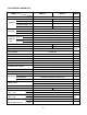
CONTENTS 2.4 REFRIGERATION CYCLE............................12 2.4.1 CONDENSER ......................................12 2.4.2 EVAPORATOR ....................................12 2.4.3 CAPILLARY TUBE...............................12 1. PREFACE 1.1 SAFETY PRECAUTIONS ...............................2 1.2 INSULATION RESISTANCE TEST.................2 1.3 SPECIFICATIONS ..........................................3 1.4 FEATURES .....................................................6 1.5 CONTROL LOCATIONS ............
1.3 SPECIFICATIONS 1.3.1 FOR BD-81/BD-101 MODELS BD-81 BD101 REMARK ITEMS POWER SUPPLY 1Ø, 115V, 60Hz COOLING CAPACITY (Btu/h) 8,000 10,000 INPUT (W) 800 1,050 RUNNING CURRENT (A) 7.5 9.8 (Btu/w.h) 10.0 9.5 380(13.2 OZ) 410(14.5 OZ) E.E.R REFRIGERANT (R-22) CHARGE(g) OPERATING TEMPERATURE INDOOR (°C) 26.7(DB) 19.4(WB) OUTDOOR (°C) 35(DB) 23.
1.3.2 FOR BD-123 MODELS BD-123 ITEMS 1Ø, 208/ 230V, 60Hz POWER SUPPLY COOLING CAPACITY 11,400/11,700 (Btu/h) INPUT (W) 1,200/1,230 RUNNING CURRENT (A) 6.2/5.8 E.E.R. 9.5 (Btu/W.h) OPERATING TEMPERA-TURE INDOOR (°C) OUTDOOR (°C) 26.7 (DB) 19.4 (WB) 35 (DB) 23.9 (WB) 465(16.
1.3.3 FOR BDE-103/BDE-123 MODELS ITEMS BDE-103 CAPACITY 9,800/10,000 11,400/11,700 (W) 1,030/1,050 1,200/1,230 5.2/4.7 6.2/5.8 9.5 9.5 RUNNING CURRENT (A) (Btu/W.h) CAPACITY HEATING (Btu/h) INPUT E.E.R. (Btu/h) 9,200/11,200 (W) 2,900/3,500 INPUT 14.0/15.3 RUNNING CURRENT (A) INDOOR (°C) OPERATING COOLING OUTDOOR (°C) TEMPERAINDOOR (°C) TURE HEATING OUTDOOR (°C) REFRIGERANT (R-22) CHARGE(g) EVAPORATOR 26.7 (DB) 19.4 (WB) 35 (DB) 23.9 (WB) 21.1 (DB) 15.6 (WB) 8.3 (DB) 6.
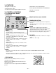
1.4 FEATURES • Designed for cooling only. • Side air-intake, side cooled-air discharge. • Powerful and quiet cooling. • Top-down chassis for the simple installation and service. • Built in adjustable THERMISTOR and THERMOSTAT. • Washable one-touch filter. • Compact size. 1.5 CONTROL LOCATIONS 1.5.1 COOLING ONLY MODEL • OPERATION REMOTE CONTROL SIGNAL RECEIVER TEMPERATURE SETTING • Use this button to automatically control the temperature of the room.
1.5.2 COOLING AND HEATING MODEL • OPERATION Off Fan Only Low Cool High Cool Low Heat High Heat - Turns the air conditioner off. - The low fan speed operation without cooling (heating). - Cooling with the low speed fan operation. - Cooling with the high speed fan operation. - Heating with the low speed fan operation. - Heating with the high speed fan operation. Turn the Temperature Knob to the desired setting. The central position is a normal setting for average conditions.
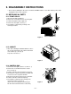
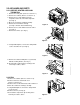
2. DISASSEMBLY INSTRUCTIONS — Prior to disassembling the unit, make sure that the POWER switch is set to OFF and the power cord is unplugged from the wall receptacle. 2.1 MECHANICAL PARTS 2.1.1 FRONT GRILLE 1. Open the inlet grille downward. 2. Remove the screw which fastens the front grille. 3. Pull the front grille from the right side. 4. Remove the front grille. (See Fig. 1) 5. Re-install the component by referring to the removal procedure. Figure 1 2.1.2 CABINET 1.
2.2 AIR HANDLING PARTS 2.2.1 ORIFICE, HEATER ASSY AND TURBO FAN 1. Remove the front grille. (Refer to section 2.1.1) 2. Remove the cabinet. (Refer to section 2.1.2) 3. Remove the 2 screws which fasten the evaporator at the left side and the right side. (See Fig. 4) 4. Move the evaporator sideward carefully. 5. Remove the 2 terminals carefully (See Fig. 5, Electric Heater Model only) 6. Remove the 4 screws which fasten the orifice. (See Fig. 5) 7. Remove the orifice. (See Fig. 5) Figure 4 Figure 5 8.
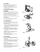
2.2.3 SHROUD 1. Remove the fan. (Refer to section 2.2.2) 2. Remove the screw which fastens the shroud. 3. Remove the shroud. (See Fig. 9) 4. Re-install the components by referring to the removal procedures, above. 2.3 ELECTRICAL PARTS 2.3.1 MOTOR 1. Remove the cabinet. (Refer to section 2.1.2) 2. Remove the clamp cord and disconnect the wire housing in control box. (Refer to section 2.1.3) 3. Remove the turbo fan. (Refer to section 2.2.2) 4. Remove the fan. (Refer to section 2.2.2) 5.
2.3.4 POWER CORD 1. Remove the control box. (Refer to section 2.1.3) 2. Unfold the control box. (Refer to section 2.3.3) 3. Disconnect the grounding screw from the control box. 4. Disconnect 2 receptacles. 5. Remove a screw which fastens the clip cord. 6. Pull the power cord. (See Fig. 13) 7. Re-install the components by referring to the removal procedure, above. (Use only one ground-marked hole, , for ground connection.) 8.
2.4 REFRIGERATION CYCLE CAUTION Discharge the refrigerant system using a FreonTM Recovery System. If there is no valve to attach the recovery system, install one (such as a WATCO A-1) before venting the FreonTM. Leave the valve in place after servicing the system. 2.4.1 CONDENSER 1. Remove the cabinet. (Refer to section 2.1.2) 2. Remove the brace and the shroud cover. (Refer to section 2.2.1) 3. Remove the 5 screws which fasten the condenser. 4.
NOTES — Replacement of the refrigeration cycle. 1. When replacing the refrigeration cycle, be sure to discharge the refrigerant system using a FreonTM recovery System. If there is no valve to attach the recovery system, install one (such as a WATCO A-1) before venting the FreonTM. Leave the valve in place after servicing the system. 2. After discharging the unit completely, remove the desired component, and unbrace the pinch-off tubes. 3.
Equipment needed: Vacuum pump, Charging cylinder, Manifold gauge, Brazing equipment. Pinch-off tool capable of making a vapor-proof seal, Leak detector, Tubing cutter, Hand Tools to remove components, Service valve.
3. INSTALLATION 3.1 INSTALLATION REQUIREMENTS INSTALLATION HARDWARE If you use an existing wall sleeve, you should measure its dimensions. Install the new air conditioner according to these installation instructions to achieve the best performance. All wall sleeves used to mount the new air conditioner must be in good structural condition and have a compatible rear grille in order to securely attach the new air conditioner. (FIG.
3.2 INSTALLATION NOTE: All wall sleeves used to mount the new Air Conditioner must be in sound structural condition and have a compatible rear grille that securely attaches to sleeve, or rear flange that serves as a stop for the Air Conditioner. CAUTION We strongly recommend the removal of the old wall sleeve and the installation of a new FRIEDRICH USC Wall Sleeve. If you decide to keep the existing wall sleeve, you have to redirect the louvers at the back of the wall sleeve illustration.
3.3 PROCEDURE A 1 If you are using a new USC sleeve in conjunction with your unit, skip to step 3. Otherwise, install the plastic grille from the kit. Cut the plastic grille to fit the rear opening of the existing sleeve. Place the plastic grille to the inside of the wall sleeve at the rear flange. 4 Install the new unit into the wall sleeve. 5 To assemble trim, snap the tab of each piece into the slot of the other piece as shown below.
3.4 PROCEDURE B 1 4 Redirect the louvers at the back of the wall sleeve to 60° angle as shown in the FIG 25. The use of pliers is recommended. Remove the backing from the Horizontal Insulation strip 13/8 x 5/8 x 273/16 and attach that to the inside bottom of the sleeve as shown below. Remove the backing from the Around Insulation strip 13/8 x 3/4 x 611/2 and attach that to the inside front of the sleeve as shown below.
PROCEDURE B 8 To assemble trim, snap the tab of each piece into the slot of the other piece as shown below. Slide trim over the front of the air conditioner until trim is flush with sleeve as shown below. Trim (2 ea) Wall FIG. 31 CAUTION • Air conditioners covered in this manual pose an excessive weight hazard. Two or more people are needed to move and install the unit. To prevent injury or strain, use proper lifting and carrying techniques when moving unit.
3.5 PROCEDURE C 1 4 Redirect the louvers at the back of the wall sleeve to 60° angle as shown in the FIG 32. The use of pliers is recommended. Remove the backing from the Horizontal Insulation strip 13/8 x 13/8 x 273/16 and attach that to the inside bottom of the sleeve as shown below. Remove the backing from the Around Insulation strip 13/8 x 13/8 x 611/2 and attach that to the inside front of the sleeve as shown below.
PROCEDURE C 7 9 Remove the backing from the 13" shim strips and attach them as shown below in Fig. 39. The higher portion of shim is to be placed in front of the rib on the base of wall sleeve. 1" high To assemble trim, snap the tab of each piece into the slot of the other piece as shown below. Slide trim over the front of the air conditioner until trim is flush with sleeve as shown below. 3 /4" High FIG. 38 Trim (2 ea) Shim (2EA) Wall 6" 6" FIG.
3.4 ELECTRICAL REQUIREMENTS 3.4.1 ELECTRICAL DATA (FOR 115V MODEL) Line Cord Plug Do not under any circumstances cut or remove the grounding prong from the plug. Power supply cord with 3-prong grounding plug Use Wall Receptacle Parallel type Power Supply Use 15 AMP time delay fuse or 15 AMP circuit breaker. Standard 125V, 3-wire grounding receptacle rated 15A, 125V AC USE OF EXTENSION CORDS Because of potential safety hazards, we strongly discourage the use of an extension cord.
4. TROUBLESHOOTING GUIDE 4.1 OUTSIDE DIMENSIONS 24-21/32" (626mm) 14-13/32" (366mm) 19-21/32" (499mm) 4.2 PIPING SYSTEM CONDENSER COILS FAN CAPILLARY TUBE MOTOR COMPRESSOR TURBO FAN EVAPORATOR COILS : REFRIGERANT FLOW Following is a brief description of the important components and their functions in the refrigeration system. Refer to Fig. 41 to follow the refrigeration cycle and the flow of the refrigerant in the cooling cycle.
4.3 TROUBLESHOOTING GUIDE In general, possible trouble is classified in two causes. The one is called Starting Failure which is caused from an electrical defect, and the other is Ineffective Air Conditioning caused by a defect in the refrigeration circuit and improper application. Unit is running but cooling is ineffective Ineffective Cooling Check cold air circulation for smooth flow. Check outdoor coil (heat exchanger) & the fan operation. Dirty indoor coil (Heat exchanger) Check gas leakage.
Fails to Start Check power source. Check circuit breaker and fuse. Check control switch setting. Gas leakage at feeler bulb of thermostat Check control switch. Only compressor fails to start. Only fan fails to start. Improper wiring. Drop in power voltage. Improper thermostat setting Defect of fan motor capacitor. Defective compressor capacitor. Loose terminal connection. Check capacitor. Irregular motor resistance ( ). Irregular motor insulation ( ). Improper wiring Replacement.
COMPLAINT Fan motor will not run. CAUSE REMEDY No power Check voltage at outlet. Correct if none. Power supply cord Check voltage to rotary switch. If none, check power supply cord. Replace cord if circuit is open. Rotary switch Check switch continuity. Refer to wiring diagram for terminal identification. Replace switch if defective. Wire disconnected or connection loose Connect wire. Refer to wiring diagram for terminal identification. Repair or replace loose terminal.
COMPLAINT Compressor will not run, but fan motor runs. CAUSE REMEDY Voltage Check voltage. See the limits on the preceding. page. If not within limits, call an electrician. Wiring Check the wire connections, if loose, repair or replace the terminal. If wires are off, refer to wiring diagram for identification, and replace. Check wire locations. If not per wiring diagram, correct. Rotary Check for continuity, refer to the wiring diagram for terminal identification.
COMPLAINT Compressor cycles on overload. Insufficient cooling or heating Excessive noise. REMEDY CAUSE Voltage Check the voltage. See the limits on the preceding page. If not within limits, call an electrician. Overload Check overload, if externally mounted. Replace if open. (If the compressor temperature is high, remove the overload, cool, and retest.) Fan motor If not running, determine the cause. Replace if required. Condenser air flow restriction Remove the cabinet.
5. SCHEMATIC DIAGRAM 5.1 CIRCUIT DIAGRAM • MODEL : BD-81/BD-101/BD-123 CAPACITOR 2 CN-AC/DC 1 DC PCB ASSEMBLY YL 3 F C TRANS (SMPS) OR(BR) BK CN-TH1 FUSE 250V/T2A (115V/T2A) ZNR01J WH(BL) (Ribbed) GN/YL (GN) DC12V CN-HVB 3 R COMP. 4 S BL C OLP SWITCH 4 CN-12V BK(BR) (Plain) 6 THERMISTOR CN-PWR RD H RY-COMP H.V. ASSEMBLY BK RD AC PCB ASSEMBLY AIR FILTER ASSEMBLY 5 WIRING DIAGRAM NO.
• MODEL : BDE-103/BDE-123 POWER INPUT BK(BR) (Plain) WH(BL) (Ribbed) ROTARY SWITCH GN/YL RD 8 7 2 1 6 L BL BL 4 H BK BK MOTOR 3 OR(BR) 2 1 CAPACITOR YL BL YL OR(BR) F THERMOSTAT H WH C 4 C 5 BK RD RD L R 7 COMP S C BR(YL) BK BK C RD RD H BL BL O.L.P RD RD FUSE LINK WIRING DIAGRAM NO. DESCRIPTION 6 HEATER 8 BI-METAL THERMOSTAT 3854AR3563D PART NO.
6.
7. REPLACEMENT PARTS LIST R: Service Parts N: Non Service parts • MODEL: BD-81/BD-101 G B C D E PART NO. LOCATION NO.
R: Service Parts N: Non Service parts • MODEL: BD-123 LOCATION NO. G B C D E 249950 268714 268712 264110 263230 W0CZZ 267110 237200 554160 550140 567502 352113 352115 352115-1 35211A 552111 352390 349001 135312 135313 147581 147582-1 147582-2 152302 349480 149980 346811 349600 148000 435301 354210 359012 554031 559010 W48602 130410 130900 749180 PART NO.
R: Service Parts N: Non Service parts • MODEL: BDE-103/BDE-123 A B C D E DESCRIPTION 249950 CONTROL BOX ASSY, SINGLE 264110 POWER CORD ASSY 266003 269310 W0CZZ 149410 REMARK BDE-103 BDE-123 4995A20131V R 2H00677U R SWITCH, ROTARY 2H00598F R THERMOSTAT ASSY 2H01127D R CAPACITOR, DRAWING 6120AR2359E R KNOB ASSY 4941A30005B R 3721A20049F R 137215 PANEL ASSY, CONTROL 554160 COMPRESSOR 550140 ISOLATOR, COMP 567502 O.L.
Specifications and performance data subject to change without notice. HEAT CONTROLLER, INC. 1900 WELLWORTH AVENUE • JACKSON, MICHIGAN 49203 THE QUALITY LEADER IN CONDITIONING AIR P/No.