HEAT CONTROLLER, INC. Through-The-Wall Air Conditioner MODELS: BGE-103A BGE-123A Service Manual CAUTION -Before servicing the unit, read the "safety precautions" in this manual. -Only for authorized service personnel.
Air Conditioner Service Manual TABLE OF CONTENTS Safety Precautions..........................................................................................................................................3 Installation .......................................................................................................................................................7 Installation requirements ................................................................................................................
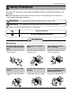
Safety Precautions Safety Precautions To prevent injury to the user or other people and property damage, the following instructions must be followed. ■ Incorrect operation due to ignoring instruction will cause harm or damage. The seriousness is classified by the following indications. WARNING This symbol indicates the possibility of death or serious injury. CAUTION This symbol indicates the possibility of injury or damage to property only. ■ Meanings of symbols used in this manual are as shown below.
Safety Precautions ■ Operation Do not place heavy object on the power cord and take care so that the cord should not be pressed. • There is danger of fire or electric shock. Do not share the outlet with other appliances. Take the power plug out if necessary, holding the head of the plug and do not touch it with wet hands. • It will cause electric shock or fire due to heat generation. • Otherwise, it may cause a fire or electrical shock.
Safety Precautions Do not operate or stop the unit by inserting or pulling out the power plug. • It will cause electric shock or fire due to heat generation. Do not damage or use an unspecified power cord. • It will cause electric shock or fire. Do not operate with wet hands or in damp environment. • It will cause electric shock.
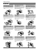
Safety Precautions ■ Operation Do not put a pet or house plant where it will be exposed to direct air flow. • It may cause injury. Do not block the inlet or outlet of air flow. • It may cause product failure. Use a soft cloth to clean. Do not use wax, thinner, or a strong detergent. • The appearance of the air conditioner may deteriorate, change color, or develop surface flaws.
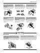
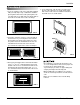
Installation Installation Remove packing sheet from the back of the sleeve, and packing corner and blue tape from the air conditioner. INSTALLATION HARDWARE 2 1 4 Installation requirements If you use an existing wall sleeve, you should measure its dimensions. Install the new air conditioner according to these installation instructions to achieve the best performance.
Installation Installation NOTICE We strongly recommend the removal of the old wall sleeve and the installation of a new HCI Wall Sleeve. If you decide to keep the existing wall sleeve, you have to redirect the louvers at the back of the wall sleeve illustration. The use of pliers is recommended. If you DO NOT redirect, you run the risk of poor performance or product failure. This is not covered under the terms of the Heat Controller warranty.
Installation Procedure A 1. If you are using the new sleeve (optionally supplied with your unit),skip to step 3. Otherwise, install the plastic grille from the kit. Cut the plastic grille to 251/2" wide and 15-1/4" high. Place the plastic grille to the inside of the wall sleeve at the rear flange. 5. To assemble trim, snap the tab of each piece into the slot of the other piece as shown below. Slide trim over the front of the air conditioner until trim is flush with sleeve as shown below. FIG.
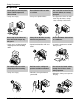
Installation Procedure B 1. Redirect the louvers at the back of the wall sleeve to 60° angle as shown in the FIG 8. The use of pliers is recommended. 4. Remove the backing from the Horizontal Insulation strip 13/8 x 5/8 x 273/16 and attach that to the inside bottom of the sleeve as shown below. Remove the backing from the Around Insulation strip 13/8 x 3/4 x 611/2 and attach that to the inside front of the sleeve as shown below.
Installation 6. Remove the backing from the support blocks and attach them to the inside of the wall sleeve as shown FIG 13. Slide the baffle into slots of the support blocks. (7 5/16") Wall Baffle Wall Sleeve Front • Air conditioners covered in this manual pose an excessive weight hazard. Two or more people are needed to move and install the unit. To prevent injury or strain, use proper lifting and carrying techniques when moving unit.
Installation Procedure C 1. Redirect the louvers at the back of the wall sleeve to 60° angle as shown in the FIG 15. The use of pliers is recommended. 4. Remove the backing from the Horizontal Insulation strip 13/8 x 13/8 x 273/16 and attach that to the inside bottom of the sleeve as shown below. Remove the backing from the Around Insulation strip 13/8 x 13/8 x 611/2 and attach that to the inside front of the sleeve as shown below.
Installation 7. Remove the backing from the 13" shim strips and attach them as shown below in Fig. 22. The higher portion of shim is to be placed in front of the rib on the base of wall sleeve. 1" high 3/ 4" High FIG. 21 Trim (2 ea) Shim (2EA) Wall 6" 6" FIG. 22 Cool Energy Saver Fan Heat F1 F2 LOW HIGH Timer MOD E 'F TEMP TIME R FAN SPEE D POW ER 8. Install the new unit into the wall sleeve 9. To assemble trim, snap the tab of each piece into the slot of the other piece as shown below.
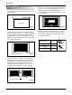
Operating Instructions Operating Instructions Controls The controls will look like one of the following. FAN SPEED • Every time you push this button, it advances the setting as follows: {High[ F2 ] → Low[ F1 ] → High[ F2 ]} Cool F1 LOW F2 HIGH Energy Saver 'F TEMPERATURE SETTING Fan Heat MODE REMOTE CONTROL SIGNAL RECEIVER Timer TIMER TEMP FAN SPEED POWER • Use this button to automatically control the temperature of the room.
Operating Instructions Remote control The remote control and control panel will look like one of the following pictures. POWER • To turn the air conditioner ON, push this button. To turn the air conditioner OFF, push the button again. • This button takes priority over any other button. Power Temp TEMPERATURE SETTING • Use this button to automatically control the temperature of the room. The temperature can be set within a range of 60°F to 86°F by increments of 1°F. • The setting appears in the display.
Operating Instructions How to insert Batteries 1. Remove the cover from the back of the remote controller. 2. Insert two batteries. • Be sure that the (+) and (-) directions are correct. • Be sure that both batteries are new. • Do not use rechargeable batteries. Such batteries differ from standard dry cells in shape, dimensions, and performance. • Remove the batteries from the remote controller if the air conditioner is not going to be used for an extended length of time. 3. Re-attach the cover.
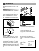
Disassembly Instructions Disassembly Instructions — Before the following disassembly, POWER SWITCH is set to OFF and disconnected the power cord. Mechanical Parts 1. FRONT GRILLE 1. Open the inlet grille upward or downward. 2. Remove the screw which fastens the front grille. 3. Pull the front grille from the right side. 4. Remove the front grille. (See Fig. 24) 5. Re-install the component by referring to the removal procedure.
Disassembly Instructions Air Handling Parts 4. ORIFICE, HEATER ASSY AND TURBO FAN 1. Remove the front grille. (Refer to section 1) 2. Remove the cabinet. (Refer to section 2) 3. Remove the 2 screws which fasten the evaporator at the left side and the right side. (See Fig. 27) 4. Move the evaporator sideward carefully. 5. Remove the 2 terminals carefully (See Fig. 28, at Electric Heater Model only) 6. Remove the 4 screws which fasten the orifice. (See Fig. 28) 7. Remove the orifice. (See Fig.
Disassembly Instructions 6. SHROUD 1. Remove the fan. (Refer to section 5) 2. Remove the screw which fasten the shroud. 3. Remove the shroud. (See Fig. 32) 4. Re-install the component by referring to the removal procedure, above. FIG. 32 Electrical Parts 7. MOTOR 1. Remove the cabinet. (Refer to section 2) 2. Remove the clamp cord and disconnect a wire housing in control box. (Refer to section 3) 3. Remove the turbo fan. (Refer to section 5) 4. Remove the fan. (Refer to section 5) 5.
Disassembly Instructions 10. POWER CORD 1. Remove the control box. (Refer to section 3) 2. Unfold the control box. (Refer to section 9) 3. Disconnect the grounding screw from the control box. 4. Disconnect 2 receptacles. 5. Remove a screw which fastens the clip cord. 6. Pull the power cord. (See Fig. 36) 7. Re-install the component by referring to the removal procedure, above. (Use only one ground-marked hole for ground connection.) 8.
Disassembly Instructions Refrigerating Cycle CAUTION Discharge the refrigerant system using FreonTM Recovery System. If there is no valve to attach the recovery system, install one (such as a WATCO A-1) before venting the FreonTM. Leave the valve in place after servicing the system. 12. CONDENSER 1. Remove the cabinet. (Refer to section 2) 2. Remove the brace and the shroud cover. (Refer to section 4) 3. Remove the 5 screws which fasten the condenser. 4.
Disassembly Instructions NOTICE — Replacement of the refrigeration cycle. 1. When replacing the refrigeration cycle, be sure to discharge the refrigerant system using a FreonTM recovery System. If there is no valve to attach the recovery system, install one (such as a WATCO A-1) before venting the FreonTM. Leave the valve in place after servicing the system. 2. After discharging the unit completely, remove the desired component, and unbrace the pinch-off tubes. 3.
Disassembly Instructions Equipment needed: Vacuum pump, Charging cylinder, Manifold gauge, Brazing equipment. Pinch-off tool capable of making a vapor-proof seal, Leak detector, Tubing cutter, Hand Tools to remove components, Service valve. COMPOUND GAUGE CONDENSER (HIGH PRESSURE SIDE) MANIFOLD GAUGE A B CAPILLARY TUBE SEE INSETS BELOW EVAPORATOR (LOW PRESSURE SIDE) COMPRESSOR LOW HI A B B A EXTERNAL VACUUM PUMP CHARGING CYLINDER C FIG.
Schematic Diagram Schematic Diagram Wiring Diagram ■ ELECTRIC HEATING MODEL 24 Room Air Conditioner
Troubleshooting Guide Troubleshooting Guide Piping System CONDENSER COILS FAN CAPILLARY TUBE MOTOR COMPRESSOR TURBO FAN EVAPORATOR COILS : REFRIGERANT FLOW Following is a brief description of the important components and their functions in the refrigeration system. Refer to Fig. 41 to follow the refrigeration cycle and the flow of the refrigerant in the cooling cycle.
Troubleshooting Guide Troubleshooting Guide In general, possible trouble is classified in two causes. The one is called Starting Failure which is caused from an electrical defect, and the other is Ineffective Air Conditioning caused by a defect in the refrigeration circuit and improper application. Unit is running but cooling is ineffective Ineffective Cooling Check of cold air circulation for smooth flow. Check of outdoor coil (heat exchanger) & the fan operation.
Troubleshooting Guide Fails to Start Check of power source. Check of circuit breaker and fuse. Check of control switch setting. Gas leakage of feeler bulb of thermostat Check of control switch. Only compressor fails to start. Only fan fails to start. Improper wiring. Drop of power voltage. Improper thermostat setting Defect of fan motor capacitor. Defect of compressor capacitor. Loose terminal connection. Check capacitor. Irregular motor resistance ( ). Irregular motor insulation ( ).
Troubleshooting Guide COMPLAINT Fan motor will not run. CAUSE REMEDY No power Check voltage at outlet. Correct if none. Power supply cord Check voltage to rotary switch. If none, check power supply cord. Replace cord if circuit is open. Rotary switch Check switch continuity. Refer to wiring diagram for terminal identification. Replace switch if defective. Wire disconnected or connection loose Connect wire. Refer to wiring diagram for terminal identification. Repair or replace loose terminal.
Troubleshooting Guide COMPLAINT Compressor will not run, but fan motor runs. CAUSE REMEDY Voltage Check voltage. See the limits on the preceding. page. If not within limits, call an electrician. Wiring Check the wire connections, if loose, repair or replace the terminal. If wires are off, refer to wiring diagram for identification, and replace. Check wire locations. If not per wiring diagram, correct. Rotary Check for continuity, refer to the wiring diagram for terminal identification.
Troubleshooting Guide COMPLAINT Compressor cycles on overload. Insufficient cooling or heating Excessive noise. CAUSE REMEDY Voltage Check the voltage. See the limits on the preceding page. If not within limits, call an electrician. Overload Check overload, if externally mounted. Replace if open. (If the compressor temperature is high, remove the overload, cool, and retest.) Fan motor If not running, determine the cause. Replace if required. Condenser air flow restriction Remove the cabinet.
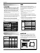
Product Specifications ITEMS MODELS REMARK POWER SUPPLY COOLING 9,800/10,000 11,200/11,500 1,040/1,060 1,270/1,310 5.2/4.7 6.4/6.0 8.8/8.8 9.4/9.4 CAPACITY (Btu/h) 9,200/11,200 INPUT (W) 2,900/3,500 RUNNING CURRENT (A) COOLING HEATING 14.0/15.3 INDOOR (°C) 26.7 (DB) 19.4 (WB) OUTDOOR (°C) 35 (DB) 23.9 (WB) INDOOR (°C) 21.1 (DB) 15.6 (WB) OUTDOOR (°C) 8.3 (DB) 6.1 (WB) REFRIGERANT (R-22) CHARGE(g) 465(16.40 OZ) 500(17.
Specifications and performance data subject to change without notice. HEAT CONTROLLER, INC. 1900 WELLWORTH AVENUE • JACKSON, MICHIGAN 49203 THE QUALITY LEADER IN CONDITIONING AIR 04/18/07 P/No.