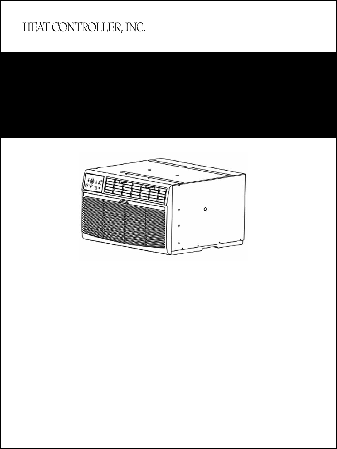
SERVICE MANUAL Thru-the-Wall Series with R-410A BG-81G BG-101G BG-103G BG-123G BGE-103G BGE-123G BG-143G Heat Controller, Inc. • 1900 Wellworth Ave. • Jackson, MI 49203 • (517)787-2100 • www.heatcontroller.
Service Manual Room Air Conditioner with R-410A Heat Controller, Inc. Table of Contents 1. PRECAUTION.........................................................................................................................2 1.1 Safety precaution............................................................................................................2 1.2 Warning..........................................................................................................................2 1.3 Caution........
Service Manual Room Air Conditioner with R-410A Heat Controller, Inc. 1. PRECAUTION 1.1 Safety precaution To prevent injury to the user and property damage, the following instructions must be followed. Incorrect operation may cause harm or damage. Before servicing unit, be sure to read this service manual. 1.2 Warning Do not use damaged power cords, plugs, or a loose socket. Always use the power plug and socket with the ground terminal. Do not modify or extend the power cord.
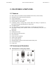
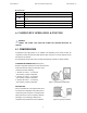
Service Manual Room Air Conditioner with R-410A Heat Controller, Inc. 2. FEATURES AND PANEL 2.1 Features Slide-in and Top-out chassis for simple installation and service (on some models). Washable one-touch filter and easy access panel. Super compact design. Reliable and efficient rotary compressor. Fresh air switch (on some models). Anti-freezing control in cooling mode. Prevents water from freezing on evaporator by sensing the evaporator pipe temperature in cooling mode.
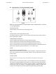
Service Manual Room Air Conditioner with R-410A Heat Controller, Inc. Control panel for cooling and heating models: B Panel Note: The control panels above are representative of many available models. Your model may be slightly different. On/Off (On and Off): Press this button once to start the unit, press again to stop. FAN: Press this button to select appropriate fan speed. Fan Speed mode has four options - Auto, Low, Med or High. Each time the button is pressed, the fan speed mode is shifted.
Service Manual Room Air Conditioner with R-410A Heat Controller, Inc. TIMER: Press this button to set the time for unit starting or stopping. Press or hold the Up (▲) / Down (▼) to set the timer time. Turning the unit ON or OFF at any time will cancel the Auto Start/Stop function. CHECK FILTER: This feature is a reminder to clean the Air Filter for more efficient operation. The “CHECK FILTER” light will illuminate after 250 hours of operation.
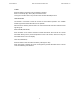
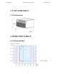
Service Manual Room Air Conditioner with R-410A Heat Controller, Inc. 3. UNIT DIMENSION 3.1 Unit dimension: 4. OPERATION LIMITS 4.
Service Manual Room Air Conditioner with R-410A Heat Controller, Inc. Note: The chart is the result from the continuous operation under constant air temperature conditions. However, the initial pull-down stage is not included. 4.2 Electric heating operation Indoor air temp DB Outdoor air temp DB Note: The chart is the result from the continuous operation under constant air temperature conditions. However, the initial pull-down stage is not included.
Service Manual Room Air Conditioner with R-410A Heat Controller, Inc. 5. PROTECTION FUNCTION 5.1 Symbol & Meaning TA: Indoor ambient temperature; TE: Indoor evaporator temperature; TS: Setting temperature through the remote controller. 5.2 Protection Function 3 minute compressor time delay The compressor will wait for 3 minutes before restarting, so as to prevent the pressure imbalance in refrigerant system from resulting in compressor rotor locking.
Service Manual Room Air Conditioner with R-410A Heat Controller, Inc. Fault Code Defect code Ed AS Defect explanation Evaporator de-frosting defect. Indoor ambient temperature sensor failure in heating, cooling, dry and auto mode. HS DAHT sensor failure in heating mode. LO Sensor disconnection malfunction in fan only mode HI Sensor short circuit malfunction in fan only mode 6. COMPONENT OPERATION & TESTING WARNING: DISCONNECT THE POWER CORD FROM THE POWER PLUG BEFORE SERVICING OR TESTING. 6.
Service Manual Room Air Conditioner with R-410A Heat Controller, Inc. CHECKING COMPRESSOR EFFICIENCY The reason for compressor inefficiency is normally due to broken or damaged suction and/or discharge valves, reducing the ability of the compressor to pump refrigerant gas. This condition can be checked as follows: 1. Install a piercing valve on the suction and discharge or liquid process tube. 2. Attach gauges to the high and low sides of the system. 3.
Service Manual Room Air Conditioner with R-410A Heat Controller, Inc. CHECKING THE INTERNAL OVERLOAD (see Figure 4.) 1. With no power to unit, remove the leads from the compressor terminals. 2. Using an ohmmeter, test continuity between terminals C-S and C-R. If not continuous, the compressor overload is open and the compressor must be replaced. Figure 4: Internal overload 6.2 FAN MOTOR A single phase permanent split capacitor motor is used to drive the evaporator blower and condenser fan.
Service Manual Room Air Conditioner with R-410A Heat Controller, Inc. compressor (HERM) terminal. A satisfactory capacitor will cause a deflection on the pointer, then gradually move back to infinity. 4. Reverse the leads of the probe and momentarily touch the capacitor terminals. The deflection of the pointer should be two times that of the first check if the capacitor is good. 5. Repeat steps 3 and 4 to check fan motor capacitor.
Service Manual Room Air Conditioner with R-410A Heat Controller, Inc. 6.6 VALVE, DRAIN PAN (see Figure 7) During the cooling mode of operation, condensate which collects in the drain pan is picked up by the condenser fan blade and sprayed onto the condenser coil. This assists in cooling the refrigerant plus evaporating the water. During the heating mode of operation, it is necessary that water be removed to prevent it from freezing due to cold outside temperatures.
Service Manual Room Air Conditioner with R-410A Heat Controller, Inc. HERMETIC COMPONENT REPLACEMENT The following procedure applies when replacing components in the sealed refrigeration circuit or repairing refrigerant leaks. (Compressor, condenser, evaporator, capillary tube, refrigerant leaks, etc.) 1. Recover the refrigerant from the system at the process tube located on the high side of the system by installing a line tap on the process tube.
Service Manual Room Air Conditioner with R-410A Heat Controller, Inc. side in small increments while operating the unit. 12. Restart unit several times after allowing pressures to stabilize. Pinch off process tubes, cut and solder the ends. Remove pinch off tool, and leak check the process tube ends. SPECIAL PROCEDURE IN THE CASE OF COMPRESSOR MOTOR BURNOUT 1. Recover all refrigerant and oil from the system. 2. Remove compressor, capillary tube and filter drier from the system. 3.
Service Manual Room Air Conditioner with R-410A Heat Controller, Inc. 7. WIRING DIAGRAM The wiring diagrams listed below are representative of models deployed with full features. Your model may not offer all these features, accordingly it will slightly differ from your wiring diagram in these optional features area. Refer to the actual wiring diagram included wit your unit.
Service Manual Room Air Conditioner with R-410A Heat Controller, Inc. 8. TROUBLESHOOTING In general, problems are classified by three types. One is called Starting Failure which is caused from an electrical defect, another is ineffective Air Conditioning caused by a defect in the refrigeration circuit and improper application, and the other is called Structure Damage. 8.1 Flow Chart Display keeps showing "AS" or "HS". Check the wiring. Yes Correct or repair the wires.
Service Manual Room Air Conditioner with R-410A Heat Controller, Inc. The "filter check" lamp is on. Press "filter check" button several times and check whether the problem stops. No Replace the main control board. Button of remote controller doesn’t work. Check the power supply. No Yes Check whether the voltage of battery is lower than 2.2V. Replace with new batteries. No Check whether the failure button is locked by button holder. No Check whether the buttons on the unit work normally.
Service Manual Room Air Conditioner with R-410A Heat Controller, Inc. Operation panel doesn’t work. Check the power supply. No Press the "LED" button of remote controller several times and check whether the problem stops. No Check the wiring of display board. Yes Repair the wiring. No Replace the display board. No Replace the main control board. Follow me mode doesn’t work. Check the power supply. No Press "follow me" button several times and check whether this mode can work.
Service Manual Room Air Conditioner with R-410A Display keeps showing "Ed". Check whether the evaporator frosts. No Check whether the indoor air inlet is blocked. No Check whether the indoor ambient temperature is too low. No Check whether the indoor dust filter is too dirty. No Check whether there is too much water on the chassis. No Check the wiring of pipe temperature sensor. No Check the pipe temperature sensor. Replace the pipe temperature sensor. Replace the main control board.
Service Manual Room Air Conditioner with R-410A Heat Controller, Inc. Compressor doesn’t work. Check whether the indoor temperature is lower than 59F (15°C). No Check the power supply. No Check whether the voltage is too high or too low. No Check the wiring. No Check whether the compressor is in overload protection mode. No Check whether the relay of compressor in PCB works normally (Start the uni t, wait 3 m inutes for the compressor to turn on, and set the unit in the cool mode and 26F (17C).
Service Manual Room Air Conditioner with R-410A The fan motor doesn’t work. Check the power supply. Check whether the indoor (outdoor) fan is locked. No Check the wiring. No Check whether the relays on PCB for motor work normally. No Comparing w ith f an m otor spec ification, check the resistance of fan motor. No Replace the fan motor. Cooling mode doesn’t work or not cooling not enough. Check the operation mode. Check the set temperature. Check whether the filter is dirty/clogged.
Service Manual Room Air Conditioner with R-410A Heat Controller, Inc. The air conditioner doesn’t work. Check the power supply. No Check the wiring. No Check whether the transformer has failed. Measure the output voltage of transformer and check whether it is the range from +5V to 12V. If not, replace the transformer. No Replace the PCB. The compressor doesn’t stop, after the set temperature is reached. Check the wiring. No Check whether the unit can turn off using the remote controller.
Service Manual Room Air Conditioner with R-410A The compressor cycles on/off frequently. Check whether the airflow is blocked. No Check if the fan motor isn’t working. No Check whether capacitor of compressor is working normally. No Check whether the relay of compressor on PCB works normally. No Replace the PCB. No Check whether the capillary tube is blocked. No Replace the capillary. No Replace the compressor. Temperature controller doesn’t work or is unstable.
Service Manual Room Air Conditioner with R-410A Heat Controller, Inc. Water drips from the unit. Check whether the ambient humidity is too high. No Check whether the indoor outlet airflow foam is wet if water is dripping from the louvers. No Check whether the unit is correctly installed. No Check whether the air outlet foam is installed normally. No Check whether the foam of evaporator base is damaged. No Check whether the drain passage of evaporator is blocked. Replace if failed.
Service Manual Room Air Conditioner with R-410A Not heating or not heating enough. (Cooling and Electric Heater) Check the mode. No Check whether the airflow speed is too low. No Check the heat load of the room. No Check the specification of PTC-heater. Fan motor speed can’t change. (Electric Control) Check the wiring. No Check the capacitor of fan motor. Replace if failed. No Replace the PCB. No Check the resistance of fan motor and replace the motor if failed. Fan motor speed can’t change.
Service Manual Room Air Conditioner with R-410A Heat Controller, Inc. 8.2 General Troubleshooting PROBLEM P OSSIBLE CAUSE REMARK Check voltage at electrical outlet. Correct if No power none. Check voltage at the power cord terminal. Power supply cord Replace the power cord if none. Connect wire. Refer to wiring diagram for Wire disconnected or terminal identification. Repair or replace connection loose Fan motor doesn’t run. loose terminal.
Service Manual PROBLEM P Room Air Conditioner with R-410A OSSIBLE CAUSE Heat Controller, Inc. REMARK Air filter Clean or replace if restricted. Vent door Close if open. Determine if the unit is properly sized for Unit undersized the area to be cooled or heated. Condenser and Evaporator Clean if restricted. Check the fan capacitor and replace if not Fan motor within +/-10% of manufacturer’s rating. Take proper measures to make sure doors Room structure and windows are sealed well.
Service Manual PROBLEM P Room Air Conditioner with R-410A OSSIBLE CAUSE Heat Controller, Inc. REMARK Check the voltage. Call an electrician if not No power within correct limits of +/- 10% of nominal voltage rating required. No cooling or heating. Wiring Check terminals. Repair and correct if loose. Temperature setting Check and adjust the thermostat. Main switch setting Check and adjust the main switch setting. Check the resistance of reversing valve wire.
Service Manual Room Air Conditioner with R-410A Heat Controller, Inc. 8.3 Troubleshooting Cooling PROBLEM Compressor POSSIBLE CAUSE TO CORRECT Low voltage. Check for voltage at compressor. 115 volt does not run. and 230 volt units will operate at 10% voltage variance Thermostat not set cold enough Set thermostat to coldest position. Test or inoperative. thermostat and replace if inoperative. Compressor hums but cuts off on Hard start compressor. Direct test overload. compressor.
Service Manual PROBLEM Unit does Room Air Conditioner with R-410A POSSIBLE CAUSE Heat Controller, Inc. TO CORRECT Fuse blown or circuit tripped. Replace fuse, reset breaker. If repeats, not run. check fuse or breaker size. Check for shorts in unit wiring and components. Power cord not plugged in. Set switch correctly. System switch in "Off" position. Test for continuity in each switch position. Inoperative system switch. Check wiring and connections.
Service Manual Room Air Conditioner with R-410A PROBLEM POSSIBLE CAUSE Heat Controller, Inc. TO CORRECT Compressor Overload inoperative. Opens too Check operation of unit. Replace overload if attempts to soon. system operation is satisfactory. start, or runs Compressor attempts to start Allow a minimum of 2 minutes for pressures for short before system pressures are to equalize before attempting to restart. periods only. equalized. Cycles on Low or fluctuating voltage.
Service Manual Room Air Conditioner with R-410A PROBLEM POSSIBLE CAUSE Heat Controller, Inc. TO CORRECT Fan motor Defective motor. Check and replace. does not Open or shorted capacitor. Replace capacitor and check. operate in Condenser fan frozen to Chassis. "Constant" speed or Loose connections. Check all connections. Check voltage to fan "Auto” speed. Unit does not Check if drain pan valve is open. If not, replace. motor. Fuse link. Check fuse link for continuity. If defective, heat.
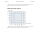
Service Manual Room Air Conditioner with R-410A Heat Controller, Inc. 9. INSTALLATION ACCESSORY LIST ▌▌Part list for CD Series: No. Part No. Part Name Quantity 1 202921890000 Grille(Aluminum) 1 2 201121890009 Grille(plastic) 1 3 201121890006 Stuffer seal 1 4 201121890007 Trim Frame(side legs) 2 5 201121890008 Trim Frame(top & bottom legs) 2 10. CHARACTERISTIC OF TEMPERATURE SENSOR Temp.°F (°C) Resistance KΩ Temp.°F (°C) Resistance KΩ Temp.°F (°C) Resistance KΩ 14 (-10) 62.
04/2009 03/2010