INSTALLATION INSTRUCTIONS Air Handler HDG Series 1.5 to 5 Ton Heat Controller, Inc. • 1900 Wellworth Ave. • Jackson, MI 49203 • (517)787-2100 • www.heatcontroller.
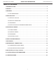
HDG Series Air Handler INSTALLATION INSTRUCTIONS Heat Controller, Inc. Table of Contents 1.0 NOMENCLATURE................................................................................................................2 2.0 SAFETY.................................................................................................................................3 3.0 GENERAL.............................................................................................................................6 3.
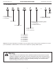
Heat Controller, Inc. HDG Series Air Handler INSTALLATION INSTRUCTIONS 1.
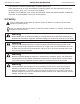
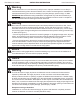
HDG Series Air Handler INSTALLATION INSTRUCTIONS Heat Controller, Inc. This document is customer property and is to remain with this unit. These instructions do not cover all the different variations systems nor does it provide for every possible contingency to be met in connection with installtion. All phases of this installation must comply with NATIONAL STATE AND LOCAL CODES. If additional information is required please contact your local distributor. 2.0 Safety This is a safety alert symbol.
Heat Controller, Inc. INSTALLATION INSTRUCTIONS HDG Series Air Handler Warning The unit must be permanently grounded. Failure to do so can result in electrical shock causing personal injury or death. Warning PROPOSITION 65: This appliance contains fiberglass insulation. Respirable particles of fiberglass are known to State of California to cause cancer. All manufacturer products meet current federal OSHA Guidelines for safety.
HDG Series Air Handler INSTALLATION INSTRUCTIONS Heat Controller, Inc. Warning Do not install this unit in manufactured (mobile) homes. Improper installation is more likely in manufactured housing due to ductwork material, size, location and arrangement. Installations in manufactured housing can cause fire resulting in property damage, personal injury or death.
Heat Controller, Inc. INSTALLATION INSTRUCTIONS HDG Series Air Handler 3.0 General The unit can be positioned for bottom return air in the upflow position, left and right return in the horizontal position, top return in downflow position. This Air Handler provides the flexibility for installation in any upflow or downflow horizontal application. The direct drive motors provides a selection of air volume to match any application. 3-Speed motors provide selections of air flow to meet desired applications.
HDG Series Air Handler Heat Controller, Inc. INSTALLATION INSTRUCTIONS 3.1 Unit Dimensions NOTE: 24” CLEARANCE IS REQUIRED IN THE FRONT OF THE UNIT FOR FILTER AND COIL MAINTENANCE.
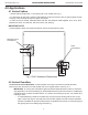
Heat Controller, Inc. HDG Series Air Handler INSTALLATION INSTRUCTIONS 4.0 Applications 4.1 Vertical Upflow • Vertical Upflow configuration is the factory set on all models (see Fig 1). • If a side return air opening is required, field fabricate a return air plenum with an opening large enough to supply unit and strong enough to support unit weight. • If return air is to be ducted, install duct flush with floor. Use fireproof resilient gasket 1/8 to 1/4 in. thick between the ducts, unit and floor.
HDG Series Air Handler INSTALLATION INSTRUCTIONS Heat Controller, Inc. • Using a screwdriver or pencil, lift blue plastic tab with hole away from breaker until breaker releases from mounting opening. • With breaker held in hand, rotate breaker so that “on” position is up, “off” position is down with unit in planned vertical mounting position. insert right wire bundle into top right breaker lug, ensuring all strands of all wires are inserted fully into lug, and no wire insulation is in lug.
Heat Controller, Inc. HDG Series Air Handler INSTALLATION INSTRUCTIONS A 1:4 ENSURE THE RETAINING CHANNEL IS FULLY ENGAGED WITH THE COIL RAIL. DETAIL A RAILS A RAILS Fig.3 VERTICAL DOWNFLOW & HORIZONTAL LEFT APPLICATIONS (lower front service panel removed “view”.
HDG Series Air Handler INSTALLATION INSTRUCTIONS Heat Controller, Inc. Caution Horizontal units must be configured for right hand air supply or left hand air supply. Horizontal drain pan must be located under indoor coil. Failure to use the drain pan can result in property damage. Conversion in Horizontal Direction: Horizontal left-hand supply can be changed to horizontal right-hand supply by removing the indoor coil and reinstalling 180° from original. 4.
Heat Controller, Inc. INSTALLATION INSTRUCTIONS HDG Series Air Handler 5.2 CONTROL WIRING IMPORTANT: Class 2 low voltage control wiring should not be run in conduit with main power wiring and must be separated from power wiring, unless class 1 wire of proper voltage rating is used. • Low voltage control wiring should be 18 Awg. color-coded. For lengths longer than 100 ft., 16 Awg. wire should be used.
HDG Series Air Handler Heat Controller, Inc. INSTALLATION INSTRUCTIONS 5.4 Electrical Data– BLOWER ONLY, NO ELECTRIC HEAT Model Voltage HP RPM SPEEDS CIRCUIT AMPS. MINIMUM CIRCUIT AMPACITY MAXIMUM CIRCUIT PROTECTOR HDG18 208/230-1-60 1/8 580 3 0.68 1 15(A) HDG24 208/230-1-60 1/5 701 3 0.95 1.5 15(A) HDG30 208/230-1-60 1/4 872 3 1.48 2 15(A) HDG36 208/230-1-60 1/2 794 3 1.63 3 15(A) HDG42 208/230-1-60 1/2 882 3 1.
Heat Controller, Inc. HDG Series Air Handler INSTALLATION INSTRUCTIONS 6.0 Airflow Performance Airflow performance data is based on cooling performance with a coil and no filter in place. Select performance table for appropriate unit size. Make sure external static applied to unit allows operation within the minimum and maximum limits shown in table below for both cooling and electric heat operation.
HDG Series Air Handler Heat Controller, Inc. INSTALLATION INSTRUCTIONS CFM (Watts) Model Number Low HDG36 Middle High Low HDG42 Middle High Low HDG48 Middle High Low HDG60 External Static Pressure-Inches W.C. [kPa] Motor Speed Middle High CFM RPM Watts Amps CFM RPM Watts Amps CFM RPM Watts Amps CFM RPM Watts Amps CFM RPM Watts Amps CFM RPM Watts Amps CFM RPM Watts Amps CFM RPM Watts Amps CFM RPM Watts Amps CFM RPM Watts Amps CFM RPM Watts Amps CFM RPM Watts Amps 0 [0] 1129 642 322 1.
Heat Controller, Inc. INSTALLATION INSTRUCTIONS HDG Series Air Handler Fan speed switch configurations: 1. All motors are shipped from the factory at medium speed as default. 2. To charge the fan speed to high speed: • Connect the black wire to the fan terminal • Connect the blue wire to the M1 terminal • Connect the red wire to the M2 terminal 3.
HDG Series Air Handler INSTALLATION INSTRUCTIONS Heat Controller, Inc. 7.0 DUCTWORK Field ductwork must comply with the National Fire Protection Association NFPA 90A, NFPA 90B and any applicable local ordinance. Warning Do not, under any circumstances, connect return ductwork to any other heat producing device such as fireplace insert, stove, etc. Unauthorized use of such devices may result in fire, carbon monoxide poisoning, explosion, personal injury or property damage.
Heat Controller, Inc. HDG Series Air Handler INSTALLATION INSTRUCTIONS 8.0 REFRIGERANT CONNECTIONS Keep the coil connections sealed until refrigerant connections are made. See the Installation Instructions for the outdoor unit for details on line sizing, tubing installation, and charging information. Coil is shipped with “No charge”. Evacuate the system before charging with refrigerant. Install refrigerant tubing so that it does not block service access to the front of the unit.
HDG Series Air Handler INSTALLATION INSTRUCTIONS Heat Controller, Inc. • The drain line should be insulated where necessary to prevent sweating and damage due to condensate forming on the outside surface of the line. • Make provisions for disconnecting and cleaning of the primary drain line should it become necessary. Install a 3 inch trap in the primary drain line as close to the unit as possible.
Heat Controller, Inc. INSTALLATION INSTRUCTIONS HDG Series Air Handler Flowrator Piston Size Chart NOTE: Pistons are factory installed for use with HRG-1D series heat pump. To use the coil with a RSG-1D series condenser, a piston change may be required. Refer to table below. Scroll Heat Pump Applications* Air Handler: Heat Pumps Piston Size HDG18FB-1A HRG18S-1D 0.052 inch HDG24FB-1A HRG24S-1D 0.058 inch HDG30FB-1A HRG30S-1D 0.065 inch HDG36FB-1A HRG36S-1D 0.
HDG Series Air Handler INSTALLATION INSTRUCTIONS Heat Controller, Inc. 9.0 AIR FILTER (not factory-installed) • External filter or other means of filtration is required. Units should be sized for a maximum of 300 feet/ min. air velocity or what is recommended for the type filter installed. Filter application and placement are critical to airflow, which may affect the heating and cooling system performance.
Heat Controller, Inc. HDG Series Air Handler INSTALLATION INSTRUCTIONS 10.0 FILTER INSTALLATION DIMENSIONS FILTER RAILS UNIT MUST BE SLIGH TLY INCLINED “H” FILTER COVER MANUAL BOLT RE TU RN AIR “ OP A” EN ING “D ” ” “B DE ” “W PT H NOTE: NOTE: AirAir Filter factory supplied filterisisNOT factory supplied (optional) Fig. Filter Base Fig.7: 6 External EXTERNAL FILTER BASE DIMENSIONAL DATA MODEL FILTER SIZE* IN [mm] HDG 18/24/30 16x20 [406x508] 16.8[426] 20.4[518] 1[25.
HDG Series Air Handler Heat Controller, Inc. INSTALLATION INSTRUCTIONS 11.0 Wiring Diagram 1. To avoid the electrical shock, connect the air conditioner with the ground lug. The main power plug in the air conditioner has been joined with the ground wiring, please don’t alter it. 2. The power socket is used as the air conditioner specially. 3. Don’t pull the power wiring hard. 4. When connecting the air conditioner with the ground, observe the local codes. 5.
Heat Controller, Inc. INSTALLATION INSTRUCTIONS Fig.
HDG Series Air Handler Heat Controller, Inc.
05/2011 04/2009