
user manual


Heat Controller, Inc. INSTALLATION INSTRUCTIONS HDG Series Air Handler
22
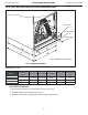
10.0 FILTER INSTALLATION DIMENSIONS
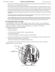
AIR FILTER REMOVAL
1.Remove bolts manually, remove air lter recover, see in Fig 7;
2. Hold the edge of the air lter and extract out .
3. Replace the lter with a properly sized lter using the table above.
NOTE:
Air filter is factory supplied (optional)
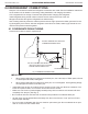
Fig. 6 EXTERNAL FILTER BASE
“H”
“W”
“B”
R
ETU
R
N
AIR
O
PE
N
IN
G
D
EPTH
“A”
“D”
FILTER RAILS
FILTER COVER
MANUAL BOLT
UNIT MUST BE SLIGHTLY INCLINED
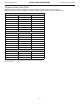
DIMENSIONAL DATA
16.8[426] 20.4[518] 1[25.4] 19.6
14.8
18.3[466] 21.6[548] 1[25.4] 20.8
16.3
20.7[526] 23.9[608] 1[25.4] 23
18.8
"H" IN [mm]
Return width
"A" IN
Return length
"B" IN
MODEL
FILTER SIZE
IN [mm]
"W" IN [mm] "D" IN [mm]
HDG 18/24/30
HDG 36/42
HDG 48/60
16x20 [406x508]
18x20 [457x508]
20x22 [508x559]
Fig. 7: External Filter Base
NOTE:
Air Filter is NOT factory supplied
*
* Air lter is not factory installed. Filter rack is provided. Field supplied lters must be installed per recommended sizes.