Installation, Operation and Maintenace Manual GeoLogix® HTS Series Split System, Two Stage, 2-5 Tons 1900 Wellworth Ave., Jackson, Michigan 49203 • Ph. 517-0787-2100 • Fax 517-787-9341 • www.heatcontroller.
H E AT C O N T R OL L E R , IN C . WATER- SOURCE HEAT PUM PS Residential Split - 60Hz R410A R e v. : 0 3 A u g u s t , 2 0 1 2 Table of Contents Model Nomenclature . . . . . . . . . . . . . . . . . . . . 3 Electrical - Line Voltage . . . . . . . . . . . . . . . . . 23 Safety . . . . . . . . . . . . . . . . . . . . . . . . . . . . . . . . 4 Electrical - Low Voltage Wiring . . . . . . . . . . . . 24 Storage . . . . . . . . . . . . . . . . . . . . . . . . . . . . . .
The Quality Leader in Conditioning Air Residential Split - 60Hz R410A R e v.
H E AT C O N T R OL L E R , IN C . WATER- SOURCE HEAT PUM PS Residential Split - 60Hz R410A R e v. : 0 3 A u g u s t , 2 0 1 2 Safety Safety Warnings, cautions and notices appear throughout this manual. Read these items carefully before attempting any installation, service or troubleshooting of the equipment. DANGER: Indicates an immediate hazardous situation, which if not avoided will result in death or serious injury. DANGER labels on unit access panels must be observed.
The Quality Leader in Conditioning Air Residential Split - 60Hz R410A R e v. : 0 3 A u g u s t , 2 0 1 2 General Information Inspection Upon receipt of the equipment, carefully check the shipment against the bill of lading. Make sure all units have been received. Inspect the packaging of each unit, and inspect each unit for damage. Insure that the carrier makes proper notation of any shortages or damage on all copies of the freight bill and completes a common carrier inspection report.
H E AT C O N T R OL L E R , IN C . WATER- SOURCE HEAT PUM PS Residential Split - 60Hz R410A R e v. : 0 3 A u g u s t , 2 0 1 2 Equipment Selection NOTICE! AHRI matched systems are required for warranty and applicable federal tax credits.
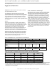
The Quality Leader in Conditioning Air Residential Split - 60Hz R410A R e v. : 0 3 A u g u s t , 2 0 1 2 Equipment Selection Air Handler Selection Example Figure 1 shows a typical performance table for a heat pump air handler. Suppose the evaporator temperature required is 50ºF, the capacity required is 35,000 Btuh and the airflow required is 1,200 CFM. Each evaporator temperature listed in the table shows three wet bulb temperatures. As recommended in the table notes above, select the 67ºF WB column.
H E AT C O N T R OL L E R , IN C . WATER- SOURCE HEAT PUM PS Residential Split - 60Hz R410A R e v. : 0 3 A u g u s t , 2 0 1 2 Installation NOTICE! Failure to remove shipping brackets from spring-mounted compressors will cause excessive noise, and could cause component failure due to added vibration.
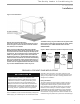
The Quality Leader in Conditioning Air Residential Split - 60Hz R410A R e v. : 0 3 A u g u s t , 2 0 1 2 Installation Figure 2: HTS Installation External Flow Controller Mounting The Flow Controller can be mounted beside the unit as shown in Figure 4. Review the Flow Controller installation manual for more details. The female locking ring is threaded onto the pipe threads which holds the male pipe end against the rubber gasket, and seals the joint.
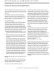
H E AT C O N T R OL L E R , IN C . WATER- SOURCE HEAT PUM PS Residential Split - 60Hz R410A R e v. : 0 3 A u g u s t , 2 0 1 2 Ground-Loop Heat Pump Applications Earth loop temperatures can range between 25 and 110°F [-4 to 43°C]. Flow rates between 2.25 and 3 gpm per ton [2.41 to 3.23 l/m per kW] of cooling capacity is recommended in these applications. Test individual horizontal loop circuits before backfilling. Test vertical U-bends and pond loop assemblies prior to installation.
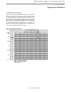
The Quality Leader in Conditioning Air Residential Split - 60Hz R410A R e v. : 0 3 A u g u s t , 2 0 1 2 Ground-Loop Heat Pump Applications Table 2: Approximate Fluid Volume (U.S. gal. [L]) per 100’ of Pipe Figure 4: Loop Connection (Indoor Compressor Section) Fluid Volume (gal [liters] per 100’ [30 meters] Pipe) Pipe Size 1” 4.1 [15.3] Copper 1.25” 6.4 [23.8] 2.5” 9.2 [34.3] 1” 3.9 [14.6] 3/4” IPS SDR11 2.8 [10.4] Rubber Hose Polyethylene Volume (gal) [liters] 1” IPS SDR11 4.5 [16.7] 1.
H E AT C O N T R OL L E R , IN C . WATER- SOURCE HEAT PUM PS Residential Split - 60Hz R410A R e v. : 0 3 A u g u s t , 2 0 1 2 Ground-Water Heat Pump Applications -Compressor Section Only Open Loop - Ground Water Systems (“Indoor” Compressor Section Only) The “outdoor” version of the compressor section may not be used with open loop systems due to potential freezing of water piping. Typical open loop piping is shown in Figure 9. Shut off valves should be included for ease of servicing.
The Quality Leader in Conditioning Air Residential Split - 60Hz R410A R e v. : 0 3 A u g u s t , 2 0 1 2 Ground-Water Heat Pump Applications Water Coil Low Temperature Limit Setting For all open loop systems the 30°F [-1.1°C] FP1 setting (factory setting-water) should be used to avoid freeze damage to the unit. See “Low Water Temperature Cutout Selection” in this manual for details on the low limit setting.
H E AT C O N T R OL L E R , IN C . WATER- SOURCE HEAT PUM PS Residential Split - 60Hz R410A R e v. : 0 3 A u g u s t , 2 0 1 2 Water Quality Standards Table 4: Water Quality Standards Water Quality Parameter HX Material Closed Recirculating Open Loop and Recirculating Well Scaling Potential - Primary Measurement Above the given limits, scaling is likely to occur. Scaling indexes should be calculated using the limits below pH/Calcium Hardness Method All - pH < 7.
The Quality Leader in Conditioning Air Residential Split - 60Hz R410A R e v. : 0 3 A u g u s t , 2 0 1 2 Refrigeration Installation CAUTION! CAUTION! R-410A systems operate at higher pressures than R-22 systems. Be certain that service equipment (gauges, tools, etc.) is rated for R-410A. Some R-22 service equipment may not be acceptable. CAUTION! CAUTION! Installation of a factory supplied liquid line bi-directional filter drier is required. Never install a suction line filter in the liquid line.
H E AT C O N T R OL L E R , IN C . WATER- SOURCE HEAT PUM PS Residential Split - 60Hz R410A R e v.
The Quality Leader in Conditioning Air Residential Split - 60Hz R410A R e v.
H E AT C O N T R OL L E R , IN C . WATER- SOURCE HEAT PUM PS Residential Split - 60Hz R410A R e v. : 0 3 A u g u s t , 2 0 1 2 Refrigeration Installation Evacuation Of The Lineset And Coil Charging The System The line set and coil must be evacuated to at least 500 microns to remove any moisture and noncondensables. Evacuate the system through both service ports in the shipping position (full CW in - see table 5) to prevent false readings on the gauge because of pressure drop through service ports.
The Quality Leader in Conditioning Air Residential Split - 60Hz R410A R e v. : 0 3 A u g u s t , 2 0 1 2 Refrigeration Installation Turn service valves full out CCW (see Table 5) and then turn back in one-half turn to open service ports. Add the required refrigerant so that the total charge calculated for the unit and line set is now in the system. Open the service valve fully counter clockwise so that the stem will backseat and prevent leakage through the schrader port while it is not in use.
H E AT C O N T R OL L E R , IN C . WATER- SOURCE HEAT PUM PS Residential Split - 60Hz R410A R e v. : 0 3 A u g u s t , 2 0 1 2 Hot Water Generator The HWG (Hot Water Generator) or desuperheater option provides considerable operating cost savings by utilizing excess heat energy from the heat pump to help satisfy domestic hot water requirements.
The Quality Leader in Conditioning Air Residential Split - 60Hz R410A R e v. : 0 3 A u g u s t , 2 0 1 2 Hot Water Generator Figure 20: Anti-Scald Valve Piping Connections The HWG is controlled by two sensors and the DXM2 microprocessor control. One sensor is located on the compressor discharge line to sense the discharge refrigerant temperature. The other sensor is located on the HWG heat exchanger’s “Water In” line to sense the potable water temperature.
H E AT C O N T R OL L E R , IN C . WATER- SOURCE HEAT PUM PS Residential Split - 60Hz R410A R e v. : 0 3 A u g u s t , 2 0 1 2 Hot Water Generator HWG Water Piping 1. Using at least 1/2” [12.7mm] I.D. copper, route and install the water piping and valves as shown in Figures 15 or 16. Install an approved anti-scald valve if the 150°F HWG setpoint is or will be selected. An appropriate method must be employed to purge air from the HWG piping.
The Quality Leader in Conditioning Air Residential Split - 60Hz R410A R e v. : 0 3 A u g u s t , 2 0 1 2 Electrical - Line Voltage All final electrical connections must be made with a length of flexible conduit to minimize vibration and sound transmission to the building. WARNING! WARNING! To avoid possible injury or death due to electrical shock, open the power supply disconnect switch and secure it in an open position during installation.
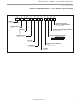
H E AT C O N T R OL L E R , IN C . WATER- SOURCE HEAT PUM PS Residential Split - 60Hz R410A R e v. : 0 3 A u g u s t , 2 0 1 2 Electrical - Low Voltage Accessory Connections Figure 22: HTS Low Voltage Field Wiring A terminal paralleling the compressor contactor coil has been provided on the DXM2 control. Terminal “A” is designed to control accessory devices. Note: This terminal should be used only with 24 Volt signals and not line voltage. Terminal “A” is energized with the compressor contactor.
The Quality Leader in Conditioning Air Residential Split - 60Hz R410A R e v. : 0 3 A u g u s t , 2 0 1 2 Electrical - Thermostat Wiring Thermostat Installation The thermostat should be located on an interior wall in a larger room, away from supply duct drafts. DO NOT locate the thermostat in areas subject to sunlight, drafts or on external walls. The wire access hole behind the thermostat may in certain cases need to be sealed to prevent erroneous temperature measurement.
H E AT C O N T R OL L E R , IN C . WATER- SOURCE HEAT PUM PS Residential Split - 60Hz R410A R e v. : 0 3 A u g u s t , 2 0 1 2 DXM2 Controls DXM2 Control DXM2 is the next generation in controls is capable of 2-way communication between itself and smart components, like the communicating thermostat, fan motor and configuration/ diagnostic tool.
The Quality Leader in Conditioning Air Residential Split - 60Hz R410A R e v. : 0 3 A u g u s t , 2 0 1 2 Figure 26a: DXM2 Layout and Connections Test Button to Speed up Time Delays Service tool Communicating connection stat connection C P1 Gnd B- A+ 24V N.C. N.O. N.O.
H E AT C O N T R OL L E R , IN C . WATER- SOURCE HEAT PUM PS Residential Split - 60Hz R410A R e v. : 0 3 A u g u s t , 2 0 1 2 Indoor Split HTS024-060 Wiring Diagram 208-230-/60/1 DXM2 28 Heat Controller, Inc.
The Quality Leader in Conditioning Air Residential Split - 60Hz R410A R e v. : 0 3 A u g u s t , 2 0 1 2 Unit Commissioning And Operating Conditions Operating Limits Environment – Units are designed for indoor installation only. Never install units in areas subject to freezing or where humidity levels could cause cabinet condensation (such as unconditioned spaces subject to 100% outside air). Power Supply – Voltage utilization shall comply with AHRI standard 110.
H E AT C O N T R OL L E R , IN C . WATER- SOURCE HEAT PUM PS Residential Split - 60Hz R410A R e v. : 0 3 A u g u s t , 2 0 1 2 Unit Start-Up and Operating Conditions Unit and System Checkout BEFORE POWERING SYSTEM, please check the following: UNIT CHECKOUT Shutoff valves: Insure that all isolation valves are open. Line voltage and wiring: Verify that voltage is within an acceptable range for the unit and wiring and fuses/breakers are properly sized. Verify that low voltage wiring is complete.
The Quality Leader in Conditioning Air Residential Split - 60Hz R410A R e v. : 0 3 A u g u s t , 2 0 1 2 Unit Start-Up Procedure SERVICE MODE the unit in the “Test” mode as shown in the unit IOM. Check for normal air temperature rise of 20°F to 30°F (heating mode).
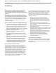
H E AT C O N T R OL L E R , IN C . WATER- SOURCE HEAT PUM PS Residential Split - 60Hz R410A R e v. : 0 3 A u g u s t , 2 0 1 2 Unit Operating Conditions Table 12: Two-Stage HFC-410A Compressor Section Coax Water Pressure Drop Model 026 038 049 064 GPM 4.0 6.0 7.0 8.0 4.0 6.0 8.0 9.0 5.5 8.3 11.0 12.0 7.0 10.5 14.0 15.0 Table 13: Water Temperature Change Through Heat Exchanger Pressure Drop (psi) 30°F 50°F 70°F 90°F 1.5 3.1 4.1 5.1 1.2 2.6 4.5 5.7 1.1 2.2 3.9 4.5 0.5 1.9 3.9 4.8 1.3 2.6 3.4 4.
The Quality Leader in Conditioning Air Residential Split - 60Hz R410A R e v. : 0 3 A u g u s t , 2 0 1 2 Unit Operating Conditions Table 14c: Size 048 HTS Two-Stage R-410A Typical Unit Operating Pressures and Temperatures Full Load Cooling - without HWG active Entering Water Temp °F Water Flow GPM/ ton Suction Pressure PSIG Discharge Pressure PSIG Superheat Subcooling 30* 1.5 2.25 3 112-122 111-121 111-121 187-207 167-187 147-167 18-23 18-23 18-23 50 1.5 2.
H E AT C O N T R OL L E R , IN C . WATER- SOURCE HEAT PUM PS Residential Split - 60Hz R410A R e v. : 0 3 A u g u s t , 2 0 1 2 Preventive Maintenance Water Coil Maintenance Condensate Drain (Direct ground water applications only) If the system is installed in an area with a known high mineral content (125 P.P.M. or greater) in the water, it is best to establish a periodic maintenance schedule with the owner so the coil can be checked regularly.
The Quality Leader in Conditioning Air Residential Split - 60Hz R410A R e v. : 0 3 A u g u s t , 2 0 1 2 Basic Troubleshooting Information General Troubleshooting Sensor: Nominal resistance at various temperatures Basic DXM2 board troubleshooting in general is best summarized as simply verifying inputs and outputs. After this process has been verified, confidence in board operation is confirmed and the trouble must be else where.
H E AT C O N T R OL L E R , IN C . WATER- SOURCE HEAT PUM PS Residential Split - 60Hz R410A R e v. : 0 3 A u g u s t , 2 0 1 2 Advanced Troubleshooting and Configuration Information General To properly configure and troubleshoot advanced control features, and to aid in troubleshooting basic control features, a communicating thermostat or diagnostic tool with similar capabilities should be used.
The Quality Leader in Conditioning Air Residential Split - 60Hz R410A R e v. : 0 3 A u g u s t , 2 0 1 2 Advanced Troubleshooting and Configuration Information Service Mode The Service Mode provides the installer with several functions for troubleshooting, including Manual Operation, Control Diagnostics, Control Configuration, and Fault History.
H E AT C O N T R OL L E R , IN C . WATER- SOURCE HEAT PUM PS Residential Split - 60Hz R410A R e v. : 0 3 A u g u s t , 2 0 1 2 DXM2 Process Flow Chart WARNING! WARNING! HAZARDOUS VOLTAGE! DISCONNECT ALL ELECTRIC POWER INCLUDING REMOTE DISCONNECTS BEFORE SERVICING. Failure to disconnect power before servicing can cause severe personal injury or death.
The Quality Leader in Conditioning Air Residential Split - 60Hz R410A R e v.
H E AT C O N T R OL L E R , IN C . WATER- SOURCE HEAT PUM PS Residential Split - 60Hz R410A R e v. : 0 3 A u g u s t , 2 0 1 2 Functional Troubleshooting Fault IFC Fault Code 13 Internal Flow Controller Fault X X Solution Improper output setting Verify the AO-2 jumper is in the PWM position No pump output signal Check DC voltage between A02 and GND - should be between 0.
The Quality Leader in Conditioning Air Residential Split - 60Hz R410A R e v.
H E AT C O N T R OL L E R , IN C . WATER- SOURCE HEAT PUM PS Residential Split - 60Hz R410A R e v.
The Quality Leader in Conditioning Air Residential Split - 60Hz R410A R e v. : 0 3 A u g u s t , 2 0 1 2 Notes: www.heatcontroller.
WATER TO BR I HE AT P U M P S A TO NE R AI NG WITH LYI MP O IR MANUFACT UR ER IFIED TO ARI A RT S C CE IS ST AND 3 ARD 1 -1 R O 25 6 Design, specifications and materials subject to change without notice. 1900 Wellworth Ave., Jackson, Michigan 49203 • Ph. 517-0787-2100 Visit us on-line at www.heatcontroller.