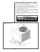
HEAT CONTROLLER INSTALLATION INSTRUCTIONS HIGH-EFFICIENCY CONDENSING UNITS FEATURING EARTH-FRIENDLY R-410A REFRIGERANT RSG - 61⁄2 & 71⁄2 TON t i n y earth friendly refrigerant WARNING [ ] INDICATES METRIC CONVERSIONS 92-42665-14-01 SUPERSEDES 92-42665-14-00
TABLE OF CONTENTS I. II. III. IV. V. VI. VII. SAFETY INFORMATION . . . . . . . . . . . . . . . . . . . . . . . . . . . . . . . . . . . . . . . . . . . 3 INTRODUCTION. . . . . . . . . . . . . . . . . . . . . . . . . . . . . . . . . . . . . . . . . . . . . . . . . . 4 CHECKING PRODUCT RECEIVED . . . . . . . . . . . . . . . . . . . . . . . . . . . . . . . . . . . 4 EQUIPMENT PROTECTION . . . . . . . . . . . . . . . . . . . . . . . . . . . . . . . . . . . . . . . . 4 WHY USE AN AIR COOLED SPLIT SYSTEM?. . . .
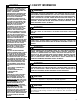
! WARNING IMPORTANT: ALL MANUFACTURER PRODUCTS MEET CURRENT FEDERAL OSHA GUIDELINES FOR SAFETY. CALIFORNIA PROPOSITION 65 WARNINGS ARE REQUIRED FOR CERTAIN PRODUCTS, WHICH ARE NOT COVERED BY THE OSHA STANDARDS. CALIFORNIA'S PROPOSITION 65 REQUIRES WARNINGS FOR PRODUCTS SOLD IN CALIFORNIA THAT CONTAIN, OR PRODUCE, ANY OF OVER 600 LISTED CHEMICALS KNOWN TO THE STATE OF CALIFORNIA TO CAUSE CANCER OR BIRTH DEFECTS SUCH AS FIBERGLASS INSULATION, LEAD IN BRASS, AND COMBUSTION PRODUCTS FROM NATURAL GAS.
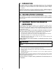
II. INTRODUCTION This booklet contains the installation and operating instructions for your self-contained air conditioner. There are a few precautions that should be taken to derive maximum satisfaction from it. Improper installation can result in unsatisfactory operation or dangerous conditions. Read this booklet and any instructions packaged with separate equipment required to make up the system prior to installation. Give this booklet to the owner and explain its provisions.
V. WHY USE AN AIR COOLED SPLIT SYSTEM? • With an air cooled system, you have no water or sewer connections to make, and no troublesome and costly water treatment problems. • Since the condensing unit is located outside the building, and the low profile air handling unit can be installed in the drop ceiling or in the conditioned space, you will not need a separate equipment room which takes up valuable building space.
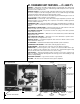
VI. STANDARD UNIT FEATURES — 61⁄2 AND 71⁄2 CABINET — Galvanized steel with a durable powder coat paint finish. The cabinet front and sides are formed into a one piece unitized design with stamped louvers to provide protection for the condenser coils. SERVICE ACCESS — Control box with separation between line and control voltages, as well as compressor and other refrigerant controls are accessible through removable top and side panels (without affecting normal operation of unit).
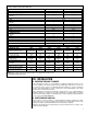
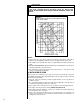
TABLE 2 PHYSICAL AND ELECTRICAL DATA TABLE (RSG) Condensing Unit Operating Weight (lbs.) [kg] Shipping Weight (lbs.) [kg] COMPRESSOR: Quantity Type RPM CONDENSER FANS: Quantity CFM [L/s] Diameter (in.) [mm] Motor Horsepower (ea.) [W] Type RPM CONDENSER COIL: Quantity Rows Fins per Inch Square Feet [m2] Fins/Tubes Tube Size, O.D. (in.) [mm] 078 264 [119.8] 283 [128.9] 090 287 [130.2] 306 [138.
C. ORDER PARTS When reporting shortages or damaged parts, or when ordering repair parts, give the complete unit model and serial numbers which are stamped on the Unit Rating Plate. D. STANDARD ITEMS The condensing unit consists of a completely assembled package which includes a compressor, a condenser coil, fan, fan motors, outdoor control box, factory wiring, factory tubing and fittings. E. INSTALLATION GENERAL NOTE: These units must be installed outdoors.
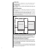
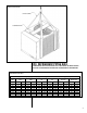
FIGURE 4 ROOFTOP INSTALLATION NYLON SLINGS SPREADER BARS VIII. REFRIGERANT PIPING DATA CONDENSING UNITS ARE SHIPPED WITH A NITROGEN HOLDING CHARGE. EVACUATE CONDENSING UNIT BEFORE CHARGING WITH REFRIGERANT. TABLE 3 REFRIGERANT PIPING DATA Equivalent Length (ft.) [m] of straight type “L” tubing for non-ferrous valves and fittings (brazed). Tube Size, O.D. 1/2 5/8 3/4 7/8 1 1/8 1 3/8 1 5/8 2 1/8 Solenoid Valve 70 72 75 78 [21.3] [21.9] [22.9] [23.8] Angle Valve 8.3 10.4 12.5 14.6 18.8 22.9 27.1 35.
! WARNING DO NOT USE OXYGEN TO PURGE LINES OR PRESSURE SYSTEM FOR LEAK TEST. OXYGEN REACTS VIOLENTLY WITH OIL, WHICH CAN CAUSE AN EXPLOSION RESULTING IN SEVERE PERSONAL INJURY OR DEATH. FIGURE 5 LIQUID LINE PRESSURE DROP PER 100 FEET EQUIVALENT LENGTH (TYPE L COPPER TUBING) NOTES: 1. When evaporator coil is above condenser, the pressure drop due to vertical lift (.5 PSIG per foot of lift) must be added to the pressure drop derived from this curve. 2.
7. Insulate the liquid line whenever the heat pick-up or transfer can affect the sub-cooling. 8. Care should be taken to avoid transmission of noise or vibration to building structure. FIGURE 6 SUCTION LINE SYSTEM CAPACITY LOSS IN PERCENT PER 100 FEET EQUIVALENT LENGTH (TYPE L COPPER TUBING) NOTES: 1. The minimum velocity line (700 fpm) is recommended for cooling only units with vertical or horizontal run refrigerant lines. 2. For suction pressure drop (PSIG), multiply percent (%) loss by 1.18. B.
5. When making up refrigerant piping, take every precaution to prevent dirt and moisture from entering the piping. 6. Locate the condensing unit and evaporator(s) as close together as possible to minimize piping runs. 7. Liquid or suction lifts not to exceed 60 ft. TABLE 4 RECOMMENDED VAPOR AND LIQUID LINE SIZES FOR VARIOUS LENGTHS OF RUN RECOMMENDED VAPOR AND LIQUID LINE SIZES FOR VARIOUS LENGTHS OF RUN EQUIVALENT LIQUID LINE O.D. VAPOR LINE O.D.
VIX. WIRING NOTE: Field wiring must comply with the National Electric Code (CEC in Canada) and any local ordinance that may apply. X. ELECTRICAL POWER It is important that proper electrical power is available at the unit. Voltage must not vary more than 10% of that stamped on the rating plate. (See Electrical Data Table for minimum and maximum voltage.) Interphase voltage variation on three-phase units must not be more than 3%.
XVI. R-410A REFRIGERANT A. TOOLS REQUIRED FOR INSTALLING & SERVICING R-410A MODELS Manifold Sets: -Up to 800 PSIG High Side -Up to 250 PSIG Low Side -550 PSIG Low Side Retard Manifold Hoses: -Service Pressure Rating of 800 PSIG Recovery Cylinders: -400 PSIG Pressure Rating -Dept. of Transportation 4BA400 or 4BW400 ! CAUTION R-410A systems operate at higher pressures than R-22 systems. Do not use R-22 service equipment or components on R-410A equipment. B.
D. REPLACEMENT UNITS To prevent failure of a new condensing unit, the existing evaporator tubing system must be correctly sized and cleaned or replaced. Care must be exercised that the expansion device is not plugged. For new and replacement units, a liquid line filter drier should be installed and refrigerant tubing should be properly sized. Test the oil for acid. If positive, a suction line filter drier is mandatory.
TABLE 5 Thermostat Load - Amps FIELD WIRE SIZE FOR 24 VOLT THERMOSTAT CIRCUITS SOLID COPPER WIRE - AWG 3.0 16 14 12 10 10 10 2.5 16 14 12 12 10 10 2.0 18 16 14 12 12 10 50 100 150 200 250 300 Length of Run - Feet (1) (1) Wire length equals twice the run distance. NOTE: The condensing unit is shipped with a holding charge of dry nitrogen which must be purged from the unit before evacuation. 1. Since the condensing unit itself must be evacuated, open the suction, discharge and liquid shut-off valves. 2.
TABLE 6 REQUIRED OZS. R-410A PER FT. OF TUBING Tube Size O.D., In. Liquid oz/ft Vapor oz/ft 1/2 5/8 3/4 7/8 1 1/8 1 3/8 1 5/8 2 1/8 1.06 1.65 2.46 3.28 0.04 0.07 0.10 0.13 0.22 0.34 0.48 0.84 Quantities based on 110°F liquid and 45°F vapor. BASIC SYSTEM CHARGE* Unit Model Basic System Charge, Oz. [g] * RSG078 178 [5046] RSG090 242 [6861] *-System with 0 Feet [0] of tubing. 15. Note weight of refrigerant tank. 16. When system has stabilized, check superheat at the suction line service valve.
FIGURE 10 ANTI-SHORT CYCLE TIMER B. LIQUID PRESSURE CONTROL Outdoor fan motor speed control designed to regulate condenser head pressure at low ambients by varying the air volume through the condenser. Has been tested and is available through the parts department. C. LIQUID LINE SOLENOID VALVE LIQUID LINE SOLENOID VALVE (24V) — Recommended for all split system applications, to prevent refrigerant migration during off cycles. See wiring connection (See Figure 11).
XX. MISCELLANEOUS A. CHARGE CHARTS FIGURE 12 RSG078 SYSTEM CHARGE CHART 61⁄2 TON CONDENSER 6-1/2 TON CONDENSING UNIT 60HZ. REFRIGERANT R-410A 525 500 115 475 110 105 450 100 425 95 Pressure at Liquid Service Port (psig) 400 90 375 85 350 80 325 75 300 70 275 65 60 250 55 225 200 175 100 105 110 115 120 125 130 135 140 145 150 155 160 165 Pressure at Suction Service Port (psig) REQUIRED OUNCES R-410A CHARGE PER FOOT OF TUBIN G VAPOR LIQUID TUBE SIZE LINE LINE O.D. IN. 1/2 1.
FIGURE 13 RSG090 SYSTEM CHARGE CHART 71⁄2 TON CONDENSER WITH 10 TON EVAPORATOR 115 500 110 475 105 450 100 Pressure at Liquid Service Port (psig) 425 95 400 90 375 85 350 80 325 75 300 70 275 Outdoor Ambient (F° DB) 525 7-1/2 TON CONDENSING UNIT 60HZ. REFRIGERANT R-410A 65 250 60 225 55 200 175 100 105 110 115 120 125 130 135 140 145 150 155 160 165 Pressure at Suction Service Port (psig) REQUIRED OUNCES R-410A CHARGE PER FOOT OF TUBIN G VAPOR LIQUID TUBE SIZE LINE LINE O.D.
B. MAINTENANCE AND OPERATION 1. All access panels must be in place when unit is in operation. 2. For maximum efficiency, the condenser coil must be kept clean. Periodic inspections, depending on local conditions are recommended. If it is necessary to clean the condenser coil, use a common garden hose. 3. Never operate the unit without filters installed in the air handler. 4. If a compressor crankcase heater is used, it must be turned on 12 hours prior to starting the compressor. 1.
C. TROUBLESHOOTING ! WARNING DISCONNECT ALL POWER TO UNIT BEFORE SERVICING. CONTACTOR MAY BREAK ONLY ONE SIDE. FAILURE TO SHUT OFF POWER CAN CAUSE ELECTRICAL SHOCK RESULTING IN PERSONAL INJURY OR DEATH. SYMPTOM POSSIBLE CAUSE Unit will not run • Power off or loose electrical connection • Thermostat out of calibration-set too high • Defective contactor • Blown fuses • Transformer defective • High pressure control open (if provided) • Interconnecting low voltage wiring damaged.
CM 1208