+($7 &21752//(5 ,1& 5RRP $LU &RQGLWLRQHU 02'(/6 RADS-51B 6HUYLFH $QG 3DUWV 0DQXDO CAUTION PRECAUTIONS IN THIS MANUAL. • ONLY FOR AUTHORIZED SERVICE PERSONNEL.
CONTENTS 1. PREFACE ...................................................................................................................................................3 1.1 FEATURES.....................................................................................................................................................3 1.2 SPECIFICATIONS .........................................................................................................................................3 1.
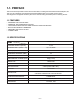
1-1. PREFACE This service manual provides various service information, including the mechanical and electrical parts, etc. This room air conditioner was manufactured and assembled under a strict quality control system. The refrigerant is charged at the factory. Be sure to read the safety precautions prior to servicing the unit. 1.
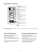
1.3 LOCATIONS OF CONTROLS Controls Temperature Setting • This button can automatically control the temperature of the room. The temperature can be set within a range of 60°F to 86°F by 1°F. Select the lower number for lower temperature of the room. Energy Saver The fan stops when the compressor stops cooling. • Approximately every 3 minutes the fan will turn on and check the room air to determine if cooling is needed.
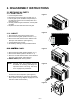
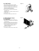
2. DISASSEMBLY INSTRUCTIONS 2.1 MECHANICAL PARTS 2.1.1 FRONT GRILLE Figure 1 1. Pull the inlet grille forward. 2. Remove the screw securing the Front Grille. (Fig. 3) 3. Push the grille up from the bottom and pull the top of the grille away from the case to lift the top tabs out of their slots. (Fig. 4) 4. Carefully position the grille, bottom first, and snap back into place. 5. Reposition the screw that secures the front grille Figure 2 2.1.2 CABINET 1. Disconnect the unit from the power source. 2.
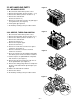
2.2 AIR HANDLING PARTS Figure 6 2.2.1 AIR GUIDE UPPER 1. Disconnect the unit from the power source. 2. Remove the front grille. (Refer to Section 2.1.1) 3. Remove the cabinet. (Refer to Section 2.1.2) 4. Remove the control board. (Refer to Section 2.1.3) 5. Remove 2 screws that secure the air guide upper to air guide lower. (See Figure 6) 6. Lift air guide upper upward. 7. Re-install by referring to the procedures above. Figure 7 2.2.2 ORIFICE, TURBO FAN AND FAN 1.
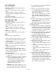
2.2.3 MOTOR Figure 10 1. Disconnect the unit from the power source. 2. Remove the front grille. (Refer to Section 2.1.1) 3. Remove the cabinet. (Refer to Section 2.1.2) 4. Remove the control board. (Refer to Section 2.1.3) 5. Remove the air guide upper. (Refer to Section 2.2.1) 6. Remove the compressor, turbo fan, fan and shroud. (Refer to Section 2.2.2) 7. Remove 2 screws that secure the motor to the motor. (See Figure 10) 8. Remove the motor. 9. Re-install by referring to the procedures above.
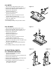
2.3.2 COMPRESSOR Figure 14 1. Remove the front grille and cabinet. (Refer to Section 2.1) 2. Discharge the refrigerant by using a refrigerant recovery system. 3. Remove the overload protector. (Refer to Section 2.3.1) 4. After discharging the unit completely, unbrace the suction and discharge pipes at the compressor connections. 5. Remove 3 nuts which fasten the compressor. 6. Remove the compressor. 7. Re-install by referring to the removal procedure above. (See Figure 14) 2.3.3 CAPACITOR 1.
Figure 18 2.3.6 POWER CORD 1. Disconnect the unit from source of power. 2. Remove the front grille. (Refer to Section 2.1.1) 3. Remove the cabinet. (Refer to Section 2.1.2) 4. Remove a screw that secures control board to base pan. (Refer to Section 2.1.3) 5. Pulls the control board toward you. 6. Disconnect the 2 receptacles and remove the grounding screw. 7. Remove a screw securing the clip with cord to the control board. 8. Pull the power cord. 9. Re-install by referring to procedures above.
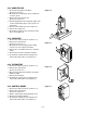
wise. This will keep oil from foaming and being drawn into the vacuum pump. 2.4.2 EVAPORATOR 1. Remove the cabinet. 2. Discharge the refrigerant by using a refrigerant recovery system. 3. Remove the air guide upper. (Refer to Section 2.2.1) 4. After discharging the refrigerant completely, unbraze the interconnecting tube at the condenser connections. 5. Remove the evaporator. 6. Re-install by referring to the procedures above. 2.4.3 CAPILLARY TUBE 1. Remove the cabinet. 2.
Equipment needed: Vacuum pump, charging cylinder, manifold gauge, brazing equipment, pinch-off tool capable of making a vapor proof seal, leak detector, tubing cutter, hand tools to remove components and service valve.
3. INSTALLATION This air conditioner is designed with a button-down chassis so it can be easily installed in a window. 3.1 SELECT THE BEST LOCATION 1. To prevent vibration and noise, make sure the unit is installed securely and firmly. 2. Install the unit where the sun does not shine directly on the unit. 3.
Installation HARDWARE 16mm TYPE B: 4EA (WOOD SCREW) 10mm TYPE A: 11EA (SHORT SCREW) TYPE D: 1EA (SEAL STRIP) TYPE E: 1EA (SASH SEAL) (Adhesive backed) (Not adhesive backed) TYPE C: 3EA (L BACKET) TYPE F: 2EA (GUIDE PANEL) 3.2.2 BEFORE INSTALLATION 1. Insert the guide panels into the guides of the air conditioner. Fasten the curtains to the unit with screws (TYPE A) as shown Figure. 25. 2. Cut the adhesive-backed seal strip (TYPE D) to the window width.
3. INSTALL THE AIR CONDITIONER IN THE WINDOW a. Carefully lift the air conditioner and slide it into the open window. Make sure the bottom guide of the air conditioner drops into the notches of the L bracket. See Figure. 28. INNER SILL TYPE A OUTER SILL INSIDE CENTER LINE 8" SHORT SIDE Figure 28 8" OUTSIDE L BRACKET IMPORTANT : When the air conditioner drops into the L bracket, the air conditioner will be centered in window opening as shown in Figure. 29. b.
REMOVAL FROM WINDOW Turn the air conditioner off, disconnect the power cord, remove the L bracket and the screws installed through the top and bottom of the guide panels, and save for reinstallation later. Close the guide panels. Keeping a firm grip on the air conditioner, raise the sash, and carefully tilt the air conditioner backward, draining any condensate water. Lift the air conditioner from the window and remove the sash seal from between the windows. 4. TROUBLESHOOTING GUIDE 4.
4.2 PIPING SYSTEM CONDENSER COILS FAN MOTOR CAPILLARY TUBE TURBO FAN EVAPORATOR COILS Figure 32 is a brief description of the important components and their function in what is called the refrigeration system. This will help you to understand the refrigeration cycle and the flow of the refrigerant in the cooling cycle.
4.3 TROUBLESHOOTING GUIDE In general, possible trouble is classified in two kinds. The one is called Starting Failure which is caused by an electrical defect. The other is Ineffective Air Conditioning caused by a defect in the refrigeration circuit and improper application. Unit is running but cooling is ineffective. Ineffective Cooling Check cold air circulation for smooth flow. Check outdoor coil (heat exchanger) and fan operation. Dirty indoor coil (heat exchanger) Check gas leakage.
Fails to Start Check of power source. Check of circuit breaker and fuse. Check of control switch setting. Gas leakage of feeler bulb of thermostat. Check control switch. Compressor fails only to start. Fan only fails to start. Drop of power voltage. Improper thermostat setting Defect of compressor capacitor. Loose terminal connection Capacitor check. Improper wiring Improper wiring. Defect of fan motor capacitor. Irregular motor resistance (Ω) Irregular motor insulation (Ω) Replacement.
ROOM AIR CONDITIONER VOLTAGE LIMITS NAME PLATE RATING MINIMUM MAXIMUM 115V ± 10% 103.5V 126.5V COMPLAINT Fan motor will not run. CAUSE REMEDY No power Check voltage at outlet. Correct if none. Power supply cord Check voltage to rotary switch. If none, check power supply cord. Replace cord if circuit is open. Rotary switch Check switch continuity. Refer to wiring diagram for terminal identification. Replace switch if defective. Wire disconnected or connection loose Connect wire.
COMPLAINT Fan motor noise. Compressor will not run, fan motor runs. CAUSE REMEDY Fan If cracked, out of balance, or partially missing, replace it. Blower If cracked, out of balance, or partially missing, replace it. Loose set screw Tighten it. Worn bearings If knocking sounds continue when running or loose, replace the motor. If the motor hums or noise appears to be internal while running, replace motor. Voltage Check voltage. See the limits on the preceding page.
COMPLAINT Compressor cycles on overload. Insufficient cooling Excessive noise CAUSE REMEDY Fan motor If not running, determine the cause. Replace if required. Condenser air flow restriction Remove the cabinet, inspect the interior surface of the condenser. If restricted, clean carefully with a vacuum cleaner (do not damage fins) or brush. Clean the interior base before re-assembling.
5. CIRCUIT DIAGRAM POWER INPUT BK(BR) WH(BL) (Plain) (Ribbed) ROTARY SWITCH 4 1 GN(GN/YL) 1 2 H BK BK 3 4 L RD RD 5 6 M BL BL 7 8 OR(BR) 2 MOTOR CAPACITOR YL YL F OR(BR) C R 3 COMP. BR S C BR BK BK RD RD BL BL 6 H 7 OLP THERMOSTAT 5 SYNC. M. 3854AR2330A WIRING DIAGRAM LOCATION YL BR BR ROCKER SWITCH DESCRIPTION PART NO. NO.
6.
Replacement Parts List RADS - 51B LocNo P/NO 130410 3041A20036G BASE ASSEMBLY,WELD R 130910 3091AR6055M CABINET ASSEMBLY,SINGLE R 135312 3531A20087D GRILLE ASSEMBLY,FRONT R 135313 3530A10039H GRILLE,INLET R 147581 4520AR3191A LINK R 147582-1 5990AR3190C LOUVER,VERTICAL R 147582-2 5990AR3190D LOUVER,VERTICAL R 149980 4998AR1608A SHROUD R 152302 5231AR2148A FILTER,AIR R 237200 3720A20017A PANEL,CONTROL 238310 3831A10001F ESCUTCHEON R R 249950 ABQ30999202 CASE AS
6SHFLILFDWLRQV DQG SHUIRUPDQFH GDWD VXEMHFW WR FKDQJH ZLWKRXW QRWLFH +($7 &21752//(5 ,1& :(//:257+ $9(18( -$&.