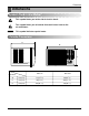
+($7 &21752//(5 ,1& webs 5RRP $LU &RQGLWLRQHU 02'(/6 5EG-71A 5EG-123A SERVICE MANUAL 6HUYLFH $QG 3DUWV 0DQXDO CAUTION • BEFORE SERVICING THE UNIT, READ THE SAFETY PRECAUTIONS IN THIS MANUAL. • ONLY FOR AUTHORIZED SERVICE PERSONNEL.
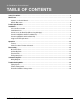
Air Conditioner Service Manual TABLE OF CONTENTS Safety Precautions..........................................................................................................................................3 Dimensions .....................................................................................................................................................5 Symbols Used in this Manual ..................................................................................................................
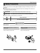
Safety Precautions Safety Precautions To prevent injury to the user or other people and property damage, the following instructions must be followed. ■ Incorrect operation due to ignoring instruction will cause harm or damage. The seriousness is classified by the following indications. WARNING This symbol indicates the possibility of death or serious injury. CAUTION This symbol indicates the possibility of injury or damage to property only. ■ Meanings of symbols used in this manual are as shown below.
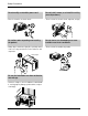
Safety Precautions Do not modify or extend the power cord. • There is risk or fire or electric shock. Do not install, remove, or re-install the unit by yourself(customer). • There is risk of fire, electric shock, explosion, or injury. Be cautious when unpacking and installing the product. • Sharp edges could cause injury. Be especially careful of the case edges and the fins on the condenser and evaporator. Do not store or use flammable gas or combustibles near the air conditioner.
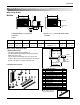
Dimensions Dimensions Symbols Used in this Manual This symbol alerts you to the risk of electric shock. This symbol alerts you to hazards that could cause harm to the air conditioner. NOTICE This symbol indicates special notes.
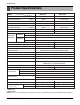
Specfications Product Specifications MODELS ITEMS POWER SUPPLY COOLING CAPACITY (Btu/h) REG-71A REG-123A 1Ø,115V, 60Hz 1Ø, 208/230V, 60Hz 6,900 11,500/12,000 INPUT (W) 710 1,170/1,220 RUNNING CURRENT (A) 6.6 5.5/5.8 (BTU/W.h) 9.7 9.8/9.8 (Btu/h) 3850 9,200/11,200 INPUT (W) 1,260 2,900/3,500 RUNNING CURRENT (A) 11.0 14.0/15.3 E.E.R HEATING CAPACITY COOLING OPERATING CONDITION HEATING 26.7 (DB)* 19.4 (WB)** INDOOR(°C) 35 (DB)* 23.9 (WB)** OUTDOOR(°C) 21.1 (DB)* 15.
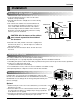
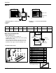
Installation Installation Select the Best Location CAUTION: All side louvers of the cabinet must remain exposed to the outside of the structure. FENCE AWNING COOLED AIR 30"~60" 1.To prevent vibration and noise, make sure the unit is installed securely and firmly. 2.Install the unit where the sunlight does not shine directly on the unit. 3.
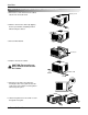
Installation How to Install(Models without Installation Kit) 1. Remove the screws that fasten the cabinet at both sides and at the back. Shipping screws On/Off On/Off Fan TIMER 2. Slide the unit from the cabinet by gripping the base pan handle and pulling forward while bracing the cabinet. ENERG SAVERY Cool Heat MODE On/Off On/Off Fan TIMER 3. Remove EPS Material. ENER GY SAVER Cool Heat MODE EPS Material On/Off On/Off Fan TIMER ENERG SAVERY Cool Heat MODE 4.
Installation How to Install(Models with Installaion Kit) When Using Gasket REG-123A A 2 A 1 2 RIGHT SIDE B B H 3 D 4 HORIZONTAL LINE E I F 1. WINDOW (WIDTH-A, HEIGHT-B) 2. GASKET 3. WALL 4. DETAILS 5.1 x 30 ROUND HEAD WOOD SCREWS A B C D E F H 625mm (245/8") 392mm (157/16") 280mm (111/32") 30mm (11/16") 0~25mm (0~1") OVER 420mm (OVER 1617/32") I 5~10mm -5~5mm (3/16"~3/8") (-3/16"~3/16") When Using Installation Kits 1.
Installation REG-71A A 2 A 1 2 G RIGHT SIDE B B C On/Off On/Off Fan Cool Heat On/Off On/Off Fan Cool TIMER Heat TIMER ENERGY MODE SAVER ENERGY MODE SAVER J H 4 D E HORIZONTAL LINE I 3 F 1. WINDOW (WIDTH-A, HEIGHT-B) 2. GASKET 3. WALL 4. DETAILS 5.
Installation Suggested Tool Requirements SCREWDRIVER (+, -), RULER, KNIFE, HAMMER, PENCIL, LEVEL Shipping screws Preparation of Chassis 1. Remove the screws that fasten the cabinet at both sides and at the back. 2. Slide the unit out from the cabinet by gripping the base pan handle and pulling forward while bracing the cabinet. 3. Remove EPS Material. 4. Cut the window sash seal to the proper length. Peel off the backing and attach the foam-pe to the underside of the window sash. 5.
Installation 3. Loosely assemble the sill support using the parts in Figure 4. INDOOR Bolt 3 OUTDOOR Sill Support 2 Nut 4 Figure 4 4. Select the position that will place the sill support near the outer most point on sill (See Figure 4) 12 Frame Guide 5 Screw(Type A) Be careful when you install the cabinet (Frame Guides are broken easily). 5. Attach the sill support to the cabinet track hole in relation to the selected position using 2 Type A screws in each support (See Figure 5).
Installation 10. Slide the unit into the cabinet.(See Fig. 8) CAUTION: For security purpose, reinstall screws (Type A) at the cabinet's sides. Power cord On/Off On/Off Fan TIMER ENERGY SAVER Cool Heat MODE Screw(Type A) Screw(Type A) 11. Cut the Foam-Strip to the proper length and insert between the upper and lower window sash. (See Fig. 9) Figure 8 Foam-Strip 8 Figure 9 12. Attach the window Locking Bracket screw. (See Fig. 10) 13 with a type C Figure 10 13.
Operation Operation Features • Designed for COOLING and HEATING. • Powerful and whispering cooling. • Slide-in and slide-out chassis for the simple installation and service. • Side air-intake, side cooled-air discharge. • Built-in adjustable THERMOSTAT • Washable one-touch filter • Compact size • Reliable and efficient rotary compressor Control Locations Function of Controls • VENTILATION The ventilation lever must be in the CLOSE position in order to maintain the best cooling conditions.
Disassembly Disassembly — Before the following disassembly, CONTROL BOX set to OFF and disconnect the power cord. Mechanical Parts 1. Front Grille 1. Open the lnlet grille upward . 2. Remove the screw that fastens the front grille. 3. Pull the front grille from the right side. 4. Remove the front grille. 5. Re-install the component by referring to the removal procedure, above.(See Figure 14) Off 5 4 High Cool Med Fan 6 7 3 8 2 Figure 14 2. Cabinet 1.
Disassembly Air Handling Parts 4. Air Guide and Turbo Fan 1. Remove the front grille. (Refer to section 1) 2. Remove the cabinet. (Refer to section 2) 3. Remove the control box. (Refer to section 3) 4. Remove the 4 screws that fasten the brace. 5. Remove the brace. 6. Remove the 2 screws that fasten the evaporator. 7. Move the evaporator forward and pulling it upward slightly. (See Figure 17) 8. Move the evaporator to the left carefully. 9. Remove the 2 terminals carefully.
Disassembly 6. Shroud 1. Remove the fan. (Refer to section 5) 2. Remove the screw that fastens the shroud. 3. Remove the shroud. (See Figure 21) 4. Re-install the component by referring to the removal procedure, above. Figure 21 Electrical Parts 7. Overload Protector 1. Remove the cabinet. (Refer to section 2) 2. Remove the nut that fastens the terminal cover. 3. Remove the terminal cover. (See Figure 22) 4. Remove all the leads from the overload protector. 5. Remove the overload protector. 6.
Disassembly 9. Capacitor 1. Remove the control box. (Refer to section 3) 2. Remove the knobs and the screw that fasten control panel from control box. 3. Remove the screw that located in the front. 4. Open the bottom side of control box. 5. Remove the screw and the clamp that fastens the capacitor. 6. Disconnect all the leads of capacitor terminals. 7. Re-install the components by referring to the removal procedure, above. (See Figure 24) 10. Power Cord 1. Remove the control box. (Refer to section 3) 2.
Disassembly 13. Motor 1. Remove the cabinet. (Refer to section 2) 2. Remove the evaporator. (Refer to section 4) 3. Remove the orifice. (Refer to section 4) 4. Remove the blower. (Refer to section 4) 5. Remove the fan. (Refer to section 5) 6. Remove the control box cover and disconnect 5 or 4 wires of motor housing. (Refer to section 3) 7. Remove the 2 or 4 screws that fasten the motor from the mount motor. (See Figure 28) 8. Remove the motor. 9.
Disassembly 16. Capillary Tube 1. Remove the cabinet. (Refer to section 2) 2. After discharging the refrigerant completely, unbraze the interconnecting tube at the capillary tube.(See caution above) 3. Remove the capillary tube. 4. Re-install the component by referring to notes. NOTICE — Replacement of the refrigeration cycle. 1. When replacing the refrigeration cycle, be sure to Discharge the refrigerant system using a FreonTM recovery System.
Disassembly Equipment needed: Vacuum pump, Charging cylinder, Manifold gauge, Brazing equipment. Pinch-off tool capable of making a leak-proof seal, Leak detector, Tubing cutter, Hand Tools to remove components, Service valve.
Schematic Diagram Schematic Diagram Wiring Diagram ■ ELECTRIC HEATING MODEL 22 Room Air Conditioner
Troubleshooting Guide Troubleshooting Guide Piping System CONDENSER COIL FAN CAPILLARY TUBE MOTOR COMPRESSOR BLOWER EVAPORATOR COIL Figure 32 is a brief description of the important components and their function in what is called the refrigeration system. This will help you to understand the refrigeration cycle and the flow of the refrigerant in the cooling cycle.
Troubleshooting Guide Troubleshooting Guide In general, possible trouble is classified in two kinds. The one is called Starting Failure which is caused from an electrical defect, and the other is ineffective Air Conditioning caused by a defect in the refrigeration circuit and improper application. Unit runs but poor cooling. Ineffective Cooling Check cold air circulation for smooth flow. Check outdoor coil (heat exchanger) & the fan operation. Dirty indoor coil (Heat exchanger) Check gas leakage.
Troubleshooting Guide Fails to Start Check of power source. Check circuit breaker and fuse. Check of control switch setting. Gas leakage of feeler bulb of thermostat Check of control switch. Compressor only fails to start. Fan only fails to start. Improper wiring. Drop of power voltage. Improper thermostat setting. Defect of fan motor capacitor. Defect of compressor capacitor. Loose terminal connection. Capacitor check. Irregular motor resistance ( ). Irregular motor insulation ( ).
Troubleshooting Guide Room Air Conditioner Voltage Limits NAME PLATE RATING 208~230±10% 115±10% COMPLAINT Fan motor will not run. MINIMUM 187V 104V CAUSE MAXIMUM 253V 126V REMEDY No power Check voltage at outlet. Correct if necessary. Power supply cord Check voltage to rotary switch. If none, check power supply cord. Replace cord if circuit is open. Rotary switch Check switch continuity. Refer to wiring diagram for terminal identification. Replace switch if defective.
Troubleshooting Guide COMPLAINT Compressor will not run, but fan motor runs. Compressor cycles on overload. Compressor cycles on overload. Compressor cycles on overload. Insufficient cooling or heating Excessive noise Auto air-swing fails. CAUSE REMEDY Thermostat Check the position of knob If not at the coldest setting, advance the knob to this setting and restart unit. Check continuity of the thermostat. Replace thermostat if circuit is open. Capacitor (Discharge capacitor before servicing.
6SHFLILFDWLRQV DQG SHUIRUPDQFH GDWD VXEMHFW WR FKDQJH ZLWKRXW QRWLFH +($7 &21752//(5 ,1& :(//:257+ $9(18( -$&.