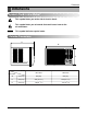
+($7 &21752//(5 ,1& webs 5RRP $LU &RQGLWLRQHU REG-183A REG-243A $QG 3DUWV 0DQXDO MANUAL 6HUYLFH SERVICE CAUTION • BEFORE SERVICING THE UNIT, READ THE SAFETY PRECAUTIONS IN THIS MANUAL. • ONLY FOR AUTHORIZED SERVICE PERSONNEL.
Air Conditioner Service Manual TABLE OF CONTENTS Safety Precautions..........................................................................................................................................3 Dimensions......................................................................................................................................................5 Product Specifications .......................................................................................................................
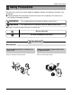
Safety Precautions Safety Precautions To prevent injury to the user or other people and property damage, the following instructions must be followed. ■ Incorrect operation due to ignoring instruction will cause harm or damage. The seriousness is classified by the following indications. WARNING This symbol indicates the possibility of death or serious injury. CAUTION This symbol indicates the possibility of injury or damage to property only. ■ Meanings of symbols used in this manual are as shown below.
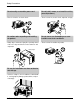
Safety Precautions Do not modify or extend the power cord. • There is risk or fire or electric shock. Do not install, remove, or re-install the unit by yourself(customer). • There is risk of fire, electric shock, explosion, or injury. Be cautious when unpacking and installing the product. • Sharp edges could cause injury. Be especially careful of the case edges and the fins on the condenser and evaporator. Do not store or use flammable gas or combustibles near the air conditioner.
Dimensions Dimensions Symbols Used in this Manual This symbol alerts you to the risk of electric shock. This symbol alerts you to hazards that could cause harm to the air conditioner. NOTICE This symbol indicates special notes.
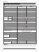
Specfications Product Specifications MODELS ITEMS POWER SUPPLY COOLING CAPACITY (Btu/h) REG-183A REG-243A 1Ø, 208/230V, 60Hz 1Ø, 208/230V, 60Hz 17,500/17,000 23,00/23,500 INPUT (W) 1,800/1,750 2,700/2,760 RUNNING CURRENT (A) 8.2/8.8 13.2/12.2 (BTU/W.h) 9.7/9.7 8.5/8.5 E.E.R HEATING CAPACITY (Btu/h) 11,600/9,400 9,400/11,600 INPUT (W) 3,100/3,670 3,750/3,770 RUNNING CURRENT (A) 15.0/16.0 15.0/16.0 OPERATING CONDITION COOLING HEATING 26.7 (DB)* INDOOR(°C) 19.
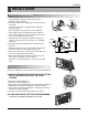
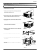
Installation INSTALLATION How to Install the unit 1/4 Bubble Level FENCE AWNING FOAM HEAT RADIATION COOLED AIR 30-60" 1. To avoid vibration and noise, make sure the unit is installed securely and firmly. 2. Install the unit where the sunlight does not shine directly on the unit. If the unit receives direct sunlight, build an awning to shade the cabinet. 3. There should be no obstacle, like a fence, within 20" which might restrict heat radiation from the condenser. 4.
Installation Window Requirements NOTICE All supporting parts should be secured to firm wood, masonry, or metal. • WINDOW REQUIREMENTS 1. This unit is designed for installation in standard double hung windows with actual opening widths from 29" to 41". The top and bottom window sashes must open sufficiently to allow a clear vertical opening of 18" from the bottom of the upper sash to the window stool. 2. The stool offset (height between the stool and sill) must be less than 1 1/4".
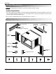
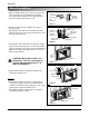
Installation Suggested tool Requirements SCREWDRIVER(+, -), RULER, KNIFE, HAMMER, PENCIL, LEVEL • PREPARATION OF CHASSIS Shipping screws 1. Remove the screws which fasten the cabinet at both sides and at the back. Keep these two screws which fasten the cabinet at both sides for later use. 2. Slide the unit out from the cabinet by gripping the base pan handle and pulling forward while bracing the cabinet. 3. Cut the window sash seal to the proper length.
Installation Cabinet Installation 1. Open the window. Mark a line on the center of the window stool between the side window stop moldings. Loosely attach the sill bracket to the support bracket using the carriage bolt and the lock nut. Sill Bracket Support Bracket Lock nut Carriage Bolt (M-Screw) Figure 5 2. Attach the sill bracket to the window sill using the screws (Type B).
Installation 5. Pull each Frame curtain fully to each window sash track, and pull the bottom window sash down behind the Top retainer bar until it meets. Screw(Type C) 6. Attach each Frame curtain the window sash by using screws (Type C). (See Fig. 10) Figure 10 7. Slide the unit into the cabinet. (See Fig. 11) CAUTION: For security purpose, reinstall screws (Type A) at cabinet's sides. Power Cord Screw Screw (Type A) Figure 11 8.
Installation Operation • VENTILATION The ventilation lever must be in the CLOSE position in order to maintain the best cooling conditions. When a fresh air is necessary in the room, set the ventilation lever to the OPEN position. The damper is opened and room air is exhausted. CLOSE VENT OPEN REMOTE CONTROLLER Power 1 Temp 5 Fan Speed 4 Timer Mode Energy Saver Auto Swing 3 2 7 6 1. POWER BUTTON To turn the air conditioner ON, push the button.
Disassembly Disassembly - Before the following disassembly, power switch is set to off and disconnected the power cord. Mechanical parts 1. Front grille 1. Open the inlet grille upward or downward. 2. Remove the screw which fastens the front grille. 3. Pull the front grille from the right side. 4. Remove the front grille. (See Fig. 16) 5. Re-install the component by referring to the removal procedure. NOTICE Mark ∆ of inlet grille means opening direction. 2. Cabinet 1.
Disassembly Air handling parts 4. Cover (at the top) 1. Remove the front grille. (Refer to section 1) 2. Remove the cabinet. (Refer to section 2) 3. Remove 11 screws which fasten the brace and covers. 4. Remove the covers and the brace. (See Fig. 19) 5. Re-install the components by referring to the removal procedure, above. Figure 19 5. Blower 1. Remove the cover. (Refer to section 4) 2. Remove the 3 screws which fasten the evaporator at the left side and the top side.(See Fig. 19) 3.
Disassembly 6. Fan 1. Remove the cabinet. (Refer to section 2) 2. Remove the brace and shroud cover. (Refer to section 4) 3. Remove the side cover with 2 screws.(See Fig. 23) 4. Remove the 5 or 6 screws which fasten the condenser. 5. Move the condenser sideways carefully. 6. Remove the clamp which secures the fan. 7. Remove the fan. (See Fig. 23) 8. Re-install the components by referring to the removal procedure, above. Figure 23 7. Shroud 1. Remove the fan. (Refer to section 6) 2.
Disassembly 10. CAPACITOR 1. Remove the control box. (Refer to section 3) 2. Remove the screw and knobs which fasten the display panel. 3. Disconnect the 2 leads from the rocker switch and remove the panel. 4. Remove a screw and unfold the control box. (See Fig. 27) 5. Remove the screw and the clamp which fastens the capacitor. (See Fig. 27) 6. Disconnect all the leads of capacitor terminals. 7. Re-install the components by referring to the removal procedure, above. Figure 27 11. POWER CORD 1.
Disassembly 13. SYNCHRONOUS MOTOR 1. Remove the control box. (Refer to section 3) 2. Unfold the control box. (Refer to section 10) 3. Remove the crankshaft. 4. Disconnect all the leads of the synchronous motor. 5. Remove the 2 screws which fasten the synchronous motor. (See Fig. 30) 6. Re-install the components by referring to the removal procedure, above.
Disassembly Refrigeration cycle CAUTION: Discharge the refrigerant system using FreonTM Recovery System.If there is no valve to attach the recovery system, install one (such as a WATCO A-1) before venting the FreonTM. Leave the valve in place after servicing the system. 16. CONDENSER 1. Remove the cabinet. (Refer to section 2) 2. Remove the brace and the shroud cover. (Refer to section 4) 3. Remove 2 screws which fasten the side cover.(See Fig. 31) 4. Remove the 5 or 6 screws which fasten the condenser. 5.
NOTICE - Replacement of the refrigeration cycle. 1. When replacing the refrigeration cycle, be sure to discharge the refrigerant system using a FreonTM recovery System. If there is no valve to attach the recovery system, install one (such as a WATCO A-1) before venting the FreonTM. Leave the valve in place after servicing the system. 2. After discharging the unit completely, remove the desired component, and unbrace the pinch-off tubes. 3.
Disassembly Equipment needed: Vacuum pump, Charging cylinder, Manifold gauge, Brazing equipment. Pin-off tool capable of making a leak-proof seal, Leak detector, Tubing cutter, Hand Tools to remove components, Service valve.
Schematic Diagram Schematic Diagram Wiring Diagram ■ ELECTRIC HEATING MODEL Service Manual 22
Troubleshooting Guide Troubleshooting Guide Piping System CONDENSER COIL FAN CAPILLARY TUBE MOTOR COMPRESSOR BLOWER EVAPORATOR COIL Figure 32 is a brief description of the important components and their function in what is called the refrigeration system. This will help you to understand the refrigeration cycle and the flow of the refrigerant in the cooling cycle.
Troubleshooting Guide Troubleshooting Guide In general, possible trouble is classified in two kinds. The one is called Starting Failure which is caused from an electrical defect, and the other is ineffective Air Conditioning caused by a defect in the refrigeration circuit and improper application. Unit runs but poor cooling. Ineffective Cooling Check cold air circulation for smooth flow. Check outdoor coil (heat exchanger) & the fan operation. Dirty indoor coil (Heat exchanger) Check gas leakage.
Troubleshooting Guide Fails to Start Check of power source. Check circuit breaker and fuse. Check of control switch setting. Gas leakage of feeler bulb of thermostat Check of control switch. Compressor only fails to start. Fan only fails to start. Improper wiring. Drop of power voltage. Improper thermostat setting. Defect of fan motor capacitor. Defect of compressor capacitor. Loose terminal connection. Capacitor check. Irregular motor resistance ( ). Irregular motor insulation ( ).
Troubleshooting Guide Room Air Conditioner Voltage Limits NAME PLATE RATING 208~230±10% 115±10% COMPLAINT Fan motor will not run. MINIMUM 187V 104V CAUSE MAXIMUM 253V 126V REMEDY No power Check voltage at outlet. Correct if necessary. Power supply cord Check voltage to rotary switch. If none, check power supply cord. Replace cord if circuit is open. Rotary switch Check switch continuity. Refer to wiring diagram for terminal identification. Replace switch if defective.
Troubleshooting Guide COMPLAINT Compressor will not run, but fan motor runs. Compressor cycles on overload. Compressor cycles on overload. Compressor cycles on overload. Insufficient cooling or heating Excessive noise Auto air-swing fails. CAUSE REMEDY Thermostat Check the position of knob If not at the coldest setting, advance the knob to this setting and restart unit. Check continuity of the thermostat. Replace thermostat if circuit is open. Capacitor (Discharge capacitor before servicing.
6SHFLILFDWLRQV DQG SHUIRUPDQFH GDWD VXEMHFW WR FKDQJH ZLWKRXW QRWLFH +($7 &21752//(5 ,1& :(//:257+ $9(18( -$&.