INSTALLATION INSTRUCTIONS SMA/SMH 18/24 Version C Single Zone Ductless Mini-Split System A/C and Heat Pump Heat Controller, Inc. • 1900 Wellworth Ave. • Jackson, MI 49203 • (517)787-2100 • www.heatcontroller.
SMA/SMH 18/24 INSTALLATION INSTRUCTIONS Heat Controller, Inc. Installation Manual for Single Zone Ductless Mini-Split • For correct installation, read this manual before starting the installation. Please save this manual in a safe place. • Only trained and qualified service personnel should install, repair or service air conditioning equipment. Users should not install the air conditioner by themselves. • Pictures in this manual may be slightly different from the air conditioner you purchased.
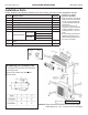
Heat Controller, Inc. SMA/SMH 18/24 INSTALLATION INSTRUCTIONS Installation Parts Please install the accessories attached with unit correctly according to this installation manual. Part No. 1 2 3 4 5 6 7 8 9 Name of Part Installation Plate Anchor Mounting Screw A (ST3.9x25-C-H) Remote Controller Remote Controller Holder Mounting Screw B (ST2.
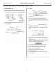
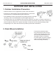
SMA/SMH 18/24 Heat Controller, Inc. INSTALLATION INSTRUCTIONS INDOOR UNIT INSTALLATION 1. Mounting Installation Plate and creating a Wall opening Installation Plate and its measurements (inches): Clearance: Clearance: Clearance: 5 inches or more 5 inches or more Clearance: Clearance: Clearance: 2. Creating a wall opening 1. Attach the installation plate A. A. B. B. C.
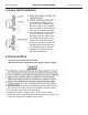
Heat Controller, Inc. SMA/SMH 18/24 INSTALLATION INSTRUCTIONS 2. Line Set and Condensate Drain Line 1. Condenstate Drain 2. Line Set A. Run the drain hose sloping downward. DO NOT install the drain hose as illustrated below. Left rear piping Right rear piping A. B. When extending the drain hose, insulate appropriately. B. left-rear-hand piping, C. • Connect the indoor unit first, then the outdoor unit. Bend and arrange the piping carefully.
SMA/SMH 18/24 INSTALLATION INSTRUCTIONS 3. Indoor Unit Installation A. B. Place the upperlip lipatatthe theback back of the indoor unit onto the upper hook of the installation plate. Move the indoor unit from side to side to see that is is secured onto the hook of the installation plate. C. Push the lower part of the indoor unit up to the wall. Then move the indoor unit from side to side and up and down to ensure it is secured to the installation plate. secured to D.
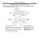
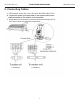
Heat Controller, Inc. INSTALLATION INSTRUCTIONS 5. Connecting Cables A. Lift the panel, loosen the screw, then open the Electric Box Cover. B. C. Wrap cables not connected to terminals with electrical tape so that they will not touch any electrical components.
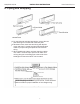
SMA/SMH 18/24 INSTALLATION INSTRUCTIONS 6. Piping and Wrapping A. For the left-hand and right-hand piping, remove the rear plate bushing from the left side of the rear plate. B. Wind the line set, drain hose and wiring with tape securely and evenly. Consult local and national electrical codes for proper routing and placement of electrical wiring. C.
Heat Controller, Inc. INSTALLATION INSTRUCTIONS SMA/SMH 18/24 OUTDOOR UNIT INSTALLATION 1. Outdoor Installation Precaution • Install the outdoor unit on a rigid base to prevent noise and vibration. • Locate the air outlet direction where the discharged air is not blocked. Ensure there are no obstacles blocking the unit’s air flow. • If the installation location is exposed to strong winds, place the unit length wise along a wall or use shield plates to protect against high winds.
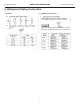
SMA/SMH 18/24 INSTALLATION INSTRUCTIONS Heat Controller, Inc. 3. Refrigerant Piping Connection 1. Flaring 2. Tightening Connection A. A. B. Hand tighten the flare nut and then tighten it with a spanner and torque wrench as shown. B. Excessive torque can break the flare nut. Ensure the proper torque is adhered to in the chart below. .
Heat Controller, Inc. INSTALLATION INSTRUCTIONS 4. Wiring Connection A. B. C. D. E. F. Use a dedicated circuit. Use HACR break sized per unit’s rating plate. Size wires according to minimum circuit ampacity shown on the unit’s rating plate. • Be sure to comply with local and national electrical codes while running the wire from the indoor unit to the outdoor unit. • Install disconnects fro the outdoor and indoor units as required by national and local electrical codes.
SMA/SMH 18/24 INSTALLATION INSTRUCTIONS Heat Controller, Inc. AIR PURGE AND TEST OPERATION 1. Air Purge A. Completely tighten the flare nuts A, B, C, D. Connect the manifold valve charge hose to the charge port of the packed valve on the gas pipe side. B. Connect the charge hose to the vacuum pump. C. D. where L=Length is entering. E. • Open the valve stem until it hits against the stop. Do not try to open it further. • Securely tighten the valve stem cap with a spanner or wrench.
Heat Controller, Inc. INSTALLATION INSTRUCTIONS 2. Gas Leak Check Make sure connections do not leak with leak detector or soapy water. soapy water. SMA/SMH 18/24 3. Test Operation Test the unit’s operation after completing gas leak check at all flare nut connections and complete an electrical safety check. A. B. C. D. E. controlled by the remote controller to run in cooling mode. Manual operation must be used when the remote controller is disabled or when maintenance is necessary. A. Lo packed valve B.
08/2010 04/2009