APPLICATION, OPERATION & MAINTENANCE MANUAL DXM2 Digital Heat Pump Controller Heat Controller, Inc. • 1900 Wellworth Ave. • Jackson, MI 49203 • (517)787-2100 • www.heatcontroller.
Application, Operation, & Maintenance Manual DXM2 UNIT CONTROLS Heat Controller, Inc. Table of Contents DXM2 Electronic Heat Pump Controls . . . . . . . . . . . . . . . . . . . . . . . . . . . . . . . . . . . . . . . . . . . . . . . . . . . . . . . . . . . . . . . . . . . . . . . . . . . .3 DXM2 Physical Dimensions & Layout . . . . . . . . . . . . . . . . . . . . . . . . . . . . . . . . . . . . . . . . . . . . . . . . . . . . . . . . . . . . . . . . . . . . . . . . . . . . 4 DXM2 Layout and Connections .
Heat Controller, Inc. DXM2 UNIT CONTROLS Application, Operation, & Maintenance Manual DXM2 Electronic Heat Pump Controls DXM2 OVERVIEW The manufacturer’s next generation control board, DXM2, is the geothermal industry’s first two-way communication. Grounding The control board must be grounded from one of the C terminals. The DXM2 electronic control is a robust, microprocessor based heat pump controller that is advanced and featureladen for maximum application flexibility.
DXM2 UNIT CONTROLS Application, Operation, & Maintenance Manual Heat Controller, Inc. DXM2 Physical Dimensions & Layout 5" C Gnd B- A+ 24V P4 N.C. N.O. P5 R Y1 (240Vac) (240Vac) P1 N.O.
DXM2 UNIT CONTROLS Heat Controller, Inc. Application, Operation, & Maintenance Manual DXM2 Layout and Connections Service tool Communicating connection stat connection C Gnd B- A+ 24V P4 N.O. Com Y2 Conventional stat connection N.C. N.O.
Application, Operation, & Maintenance Manual DXM2 UNIT CONTROLS Heat Controller, Inc. DXM2 Controls THERMOSTAT COMPATABILITY - IT IS STRONGLY RECOMMENDED THAT A COMMUNICATING THERMOSTAT (7602-443) BE USED WITH GEOMAX COMMUNICATING SYSTEMS FOR: setting for LT1 of 30°F or 10°F [-1°F or -12°C] (refrigerant temperature). Not Clipped = 30°F. Clipped = 10°F. 1. Four-wire connections between the thermostat, compressor section (HTS), and air handler (WDG). 2.
Heat Controller, Inc. DXM2 UNIT CONTROLS Application, Operation, & Maintenance Manual DXM2 Controls On = Heat Pump. Off = Heat/Cool. DIP Package #3 (S3) DIP 1.4: Thermostat Type (O/B) - Provides selection of thermostat type. Heat pump thermostats with “O” output on with Cooling or “B” output on with Heating can be selected. DIP Package #3 is 4 position and provides the following setup selections. DIP 3.1: Communications configuration: Provides selection of the DXM2 operation in a communicating system.
Application, Operation, & Maintenance Manual DXM2 UNIT CONTROLS Heat Controller, Inc. DXM2 Controls CAUTION! SAFETY FEATURES The following safety features are provided to protect the compressor, heat exchangers, wiring and other components from damage caused by operation outside of design conditions. CAUTION! Do not restart units without inspection and remedy of faulting condition. Equipment damage may occur.
Heat Controller, Inc. DXM2 UNIT CONTROLS Application, Operation, & Maintenance Manual DXM2 Controls compressor run cycle. When the Test mode is active, the Fault LED will display a fault code of 5 for a LT2 fault. When the Test mode is active, the Fault LED will display a fault code of 9 for a Swapped Thermistor fault. Fault Code 6: Condensate Overflow - The Condensate Overflow sensor must sense overflow levels for 30 continuous seconds to be recognized as a CO fault.
Application, Operation, & Maintenance Manual DXM2 UNIT CONTROLS Heat Controller, Inc. DXM2 Controls when the Heating Stage 1 demand is removed. The selected Fan output(s) will turn off after the selected heating blower off delay, and the control then reverts to Standby Mode. If there is a Master/Slave situation or a Dual Compressor situation, all Compressor relays and related functions will track with their associated DIP1.2. Note: The compressor will have a 5-minute anti-short cycle delay at power-up.
Heat Controller, Inc. DXM2 UNIT CONTROLS Application, Operation, & Maintenance Manual DXM2 Controls will change to the appropriate Heating Stage 3 airflow. With continuing Heating Stage 3 demand, EH2 will turn on after 10 minutes. EH1 and EH2 are turned off immediately when the Heating Stage 3 demand is removed, and the control reverts to Heating Stage 2 Mode.
Application, Operation, & Maintenance Manual DXM2 UNIT CONTROLS Heat Controller, Inc. DXM2 Controls airflow for the current operating mode. For the first 30 seconds of blower operation, the target airflow will be 50% of the normal target airflow. For the next 90 seconds of blower operation, the target airflow will be 75% of the normal target airflow.
DXM2 UNIT CONTROLS Heat Controller, Inc. Application, Operation, & Maintenance Manual DXM2 Controls to the compressor output. All other heat pump operating modes will operate normally, and the accessory relay will be off in all other operating modes. go to Night Setback Setpoints. Stated differently, when configured for Digital NSB Mode, the Accessory Relay directly tracks the NSB input. Thermostat Inputs – Table 5 shows the resulting demand from differing combinations of inputs.
DXM2 UNIT CONTROLS Application, Operation, & Maintenance Manual Heat Controller, Inc. DXM2 Controls counterpart to DIP1.5, meaning if H is connected to 24VAC then the selected fan outputs will operate using dehumidification speeds and airflow settings for cooling. If H is not connected to 24VAC then the selected fan outputs will operate using normal speeds and airflow settings for cooling.
DXM2 UNIT CONTROLS Heat Controller, Inc. Application, Operation, & Maintenance Manual DXM2 Controls Under Voltage, UPS or Swapped LT1/LT2) then the Fault type will only be retained if there are no “Primary” faults in memory. The Secondary Fault types will not “overwrite” the Primary fault memory. See Table 3: “LED and Alarm Relay Operation”.
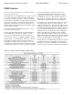
DXM2 UNIT CONTROLS Application, Operation, & Maintenance Manual Heat Controller, Inc. DXM2 Service & Application Notes Pressure Switches Table 9: Nominal resistance at various temperatures All pressure switches are designed to be normally closed during normal operating conditions, and to open upon fault. Condensate Sensor – The Condensate Sensor input will fault upon sensing impedance less than 100,000 Ohms for 30 continuous seconds.
Heat Controller, Inc. DXM2 UNIT CONTROLS Application, Operation, & Maintenance Manual DXM2 Service & Application Notes DXM2 Thermostat Details THERMOSTAT COMPATABILITY - IT IS STRONGLY RECOMMENDED THAT A COMMUNICATING THERMOSTAT (7602-443) BE USED WITH GEOMAX COMMUNICATING SYSTEMS FOR: 1. Four-wire connections between the thermostat, compressor section (HTS), and air handler (WDG). 2. Configuring, monitoring and diagnosing the system in PLAIN ENGLISH on the thermostat.
DXM2 UNIT CONTROLS Application, Operation, & Maintenance Manual Basic Troubleshooting Information General Troubleshooting Basic DXM2 board troubleshooting in general is best summarized as simply verifying inputs and outputs. After this process has been verified, confidence in board operation is confirmed and the trouble must be else where. Below are some general guidelines required for developing training materials and procedures when applying the DXM2 Control.
Heat Controller, Inc. DXM2 UNIT CONTROLS Application, Operation, & Maintenance Manual Advanced Troubleshooting and Configuration Information General To properly configure and troubleshoot advanced control features, and to aid in troubleshooting basic control features, a communicating thermostat or diagnostic tool with similar capabilities should be used.
Application, Operation, & Maintenance Manual DXM2 UNIT CONTROLS Advanced Troubleshooting and Configuration Information Service Mode The Service Mode provides the installer with several functions for troubleshooting, including Manual Operation, Control Diagnostics, Control Configuration, and Fault History.
DXM2 UNIT CONTROLS Heat Controller, Inc. Application, Operation, & Maintenance Manual Troubleshooting Chart Use the following troubleshooting flow chart to find appropriate troubleshooting strategies on the following pages for the DXM2 control and most water source heat pump applications.
DXM2 UNIT CONTROLS Application, Operation, & Maintenance Manual Heat Controller, Inc. 7602-443 024-060 DXM2 Wiring Diagram with Motorized Modulating Water Valve - Optional 96B0005N62 This diagram includes typical wiring details but is not applicable to all units. For specific unit wiring, refer to the diagram or the units’ control panel.
DXM2 UNIT CONTROLS Heat Controller, Inc. Application, Operation, & Maintenance Manual 7602-443 024-060 ‘HG’ DXM2 Wiring Diagram (Standard Installation) - 96B0005N56 This diagram includes typical wiring details but is not applicable to all units. For specific unit wiring, refer to the diagram or the units’ control panel.
DXM2 UNIT CONTROLS Application, Operation, & Maintenance Manual Heat Controller, Inc. Functional Troubleshooting CAUTION! CAUTION! Do not restart units without inspection and remedy of faulting condition. Equipment damage may occur.
DXM2 UNIT CONTROLS Heat Controller, Inc. Application, Operation, & Maintenance Manual Functional Troubleshooting (cont.
DXM2 UNIT CONTROLS Application, Operation, & Maintenance Manual Performance Troubleshooting Symptom Htg Clg Possible Cause X X Rduced or no air flow in heating X Insufficient Capacity/ Not Cooling or Heating Properly X Reduced or no air flow in cooling X X Leaky duct work X X X X X X X Low refrigerant charge Restricted metering device Defective reversing va lve Thermostat improperly located X X Unit undersized X X Scaling in water heat exchanger X X Inlet water too hot or cold Reduce
Heat Controller, Inc.
4/2012