
user manual


7
Heat Controller, Inc. DXM2 UNIT CONTROLS Application, Operation, & Maintenance Manual
On = Heat Pump. Off = Heat/Cool.
DIP 1.4: Thermostat Type (O/B) - Provides selection of
thermostat type. Heat pump thermostats with “O” output on
with Cooling or “B” output on with Heating can be selected.
On = HP Stat with O output with cooling. Off = HP Stat with
B output with heating.
DIP 1.5: Dehumidifi cation Mode - Provides selection of
normal or Dehumidifi cation Fan Mode. In Dehumidifi cation
Mode, the fan speed will be adjusted for Cooling. In Normal
Mode, the fan speed will be normal during Cooling.
On = Normal Fan Mode. Off = Dehumidifi cation Mode.
DIP 1.6: DDC Output at EH2 - DIP Switch 1.6 provides
selection for DDC operation. If set to DDC Output at EH2,
the EH2 terminal will continuously output the last fault code
of the controller. If set to EH2 normal, then the EH2 will
operate as standard electric heat output.
On = EH2 Normal. Off = DDC Output at EH2.
DIP 1.7: Boilerless Operation - Provides selection
of Boilerless Operation. In Boilerless Mode, only the
compressor is used for Heating Mode when LT1 is above
the temperature specifi ed by the setting of DIP 1.8. If DIP
1.8 is set for 50°F, then the compressor is used for heating
as long as LT1 is above 50°F. Below 50°F, the compressor
is not used and the control goes into Emergency Heat
Mode, staging on EH1 and EH2 to provide heating.
On = normal. Off = Boilerless operation.
DIP 1.8: Boilerless Changeover Temperature - Provides
selection of boilerless changeover temperature setpoint.
On = 50°F. Off = 40°F.
DIP Package #2 (S2)
DIP Package #2 (S2) - A combination of dip switches 2.1,
2.2, 2.3, and 2.4, 2.5, 2.6 deliver confi guration of ACC1
and ACC2 relay options respectively. See Table 2 for
description and functionality.
DIP 2.7: Auto Dehumidifi cation Fan Mode or High Fan
Mode - Provides selection of Auto Dehumidifi cation Fan
Mode or High Fan Mode. In Auto Dehumidifi cation Mode,
the Fan Speed will be adjusted during Cooling IF the H
input is active. In High Fan Mode, the Fan will operate on
high speed when the H input is active.
On = Auto Dehumidifi cation Mode (default). Off = High Fan
Mode.
DIP 2.8: Factory Setting - Normal position is On. Do not
change selection unless instructed to do so by the Factory.
DIP Package #3 (S3)
DIP Package #3 is 4 position and provides the following
setup selections.
DIP 3.1: Communications confi guration: Provides selection
of the DXM2 operation in a communicating system. The
DXM2 may operate as a communicating master or slave
device depending on the network confi guration. In most
confi gurations, the DXM2 will operate as a master device.
On = Communicating Master device (default). Off =
communicating Slave device.
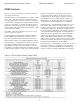
Table 2: Accessory Relay 2 Confi guration
Table 1: Accessory Relay 1 Confi guration
DXM2 Controls
DIP 2.1 DIP 2.2 DIP 2.3 ACC1 Relay Option
ON ON ON Cycle with fan
OFF ON ON Digital night setback
ON OFF ON Water valve – Slow opening
ON ON OFF Outside air damper
OFF ON OFF
Whole House Dehumidifi cation
option – Dehumidistat
OFF OFF OFF option – Humidistat
OFF OFF ON Hydronic Economizer – 1st Stage
ON OFF OFF
Hydronic Economizer – Both
Stages
All other DIP combinations are invalid
DIP 2.4 DIP 2.5 DIP 2.6 ACC2 Relay Option
ON ON ON Cycle with compressor
OFF ON ON Digital night setback
ON OFF ON Water valve – Slow opening
OFF OFF ON Humidifi er
ON ON OFF Outside air damper
All other DIP combinations are invalid
DIP 3.2: HWG Test Mode: Provides forced operation of the
HWG pump output, activating the HWG pump output for up
to fi ve minutes.
On = HWG test mode. Off = Normal HWG mode (default).
DIP 3.3: HWG Temperature: Provides the selection of the
HWG operating setpoint.
On = 150°F [66°C]. Off = 125°F [52°C] (default).
DIP 3.4: HWG Status: Provides HWG operation control.
On = HWG mode enabled. Off = HWG mode disabled
(default)