HMC30AS-1/HMH30AS-1, HMC30BS-1/HMH30BS-1Single-Zone
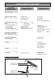
INSTALLATION OVERVIEW Installation Requirements Required Parts Required Tools The following should be always observed for safety....................3 Installation of indoor, outdoor unit................................................4 ❏ Installation plate ❏ Four type "A" screws ❏ Connecting cable Flaring work and connection of piping ...........................................6 Connection of piping(Indoor) ......7 For left rear piping For right rear piping Connection of piping(Outdoor) ..............
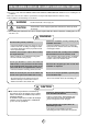
THE FOLLOWING SHOULD BE ALWAYS OBSERVED FOR SAFETY ■ Be sure to read "THE FOLLOWING SHOULD BE ALWAYS OBSERVED FOR SAFETY" before installing the air conditioner. ■ Be sure to observe the cautions specified here as they include important items related to safety. ■ The indications and meanings are as follows. WARNING : Could lead to death, serious injury, etc. CAUTION : Could lead to serious injury in particular environments when operated incorrectly.
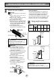
INSTALLATION OF INDOOR, OUTDOOR UNIT Read completely, then follow step by step. ■ Rooftop Installations: If the outdoor unit is installed on a roof structure, be sure to level the unit. Ensure the roof structure and anchoring method are adequate for the unit location. Consult local codes regarding rooftop mounting. If the outdoor unit is installed on root structures or walls, this may result in excessive noise and vibration, and maybe also classed as non serviceable installation.
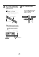
Drill a hole in the wall How to mount installation plate The wall you select should be strong and solid enough to prevent vibration A ■ Drill the piping hole with a ø70mm(0.0028in) hole core drill. Drill the piping hole at either the right or the left with the hole slightly slanted to the outdoor side. Mount the installation plate on the wall with four type A screws. If mounting the unit on a concrete wall, use anchor bolts.
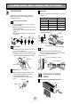
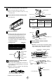
FLARING WORK AND CONNECTION OF PIPING Flaring work D ■ Carry out flaring work using flaring tool as shown below. Main cause for gas leakage is due to defect in flaring work. Carry out correct flaring work in the following procedure. Outside diameter Cut the pipes and the cable. ■ Use the piping kit accessory or the pipes purchased locally. ■ Measure the distance between the indoor and the outdoor unit. ■ Cut the pipes a little longer than measured distance. ■ Cut the cable 1.5m(59.
B Remove the front right side panel by the arrow. B ■ The connector can be disconnected by pulling it while pressing the connector's hook. ■ Remove the 1 screw for fixing low panel. Insert the connecting cable into the indoor unit from the outdoor unit through the piping hole. ■ Do not connect the cable to the indoor unit. ■ Make a small loop with the cable for easy connection later. C Main PCB Tape the tubing, drain hose and the connecting cable.
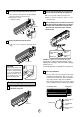
E Connecting the pipings to the indoor unit and drain hose to drain pipe. ■ Put a couple drops of refrigerant oil on the face of the flare before assembling taking care not to add any contaminants. ■ Align the center of the pipings and sufficiently tighten the flare nut by hand. Indoor unit pipe Connection pipe Vinyl tape (wide) Wrap with vinyl tape Connecting cable Pipe Indoor unit tubing Flare nut Pipings Vinyl tape(narrow) ■ Tighten the flare nut with a wrench.
C Insert the connecting cable into the indoor unit. ■ Don't connect the cable to the indoor unit. ■ Make a small loop with the cable for easy connection later. D Spanner (fixed) Flare nut Connection pipe Torque wrench Tape the drain hose and the connecting cable. Indoor unit tubing • Connecting cable Pipe Size[Torque] Capacity (Btu/h) Suction Evaporator 5/8"[6.6kg.m] 30k 3/8"[4.2kg.m] ■ When extending the drain hose at the indoor unit, install the drain pipe.
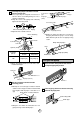
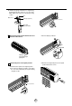
■ Bundle the piping and drain hose together by wrapping them with cloth tape over the range within which they fit into the rear piping housing section. Pipe Drain hose Vinyl tape(narrow) Green / Yellow wire Wrap with vinyl tape(wide) H B Reroute the pipings and the drain hose across the back of the chassis. ■ Connect display conductor. Main PCB Piping for passage through piping hole I ■ Refix the front right side panel to the original position with the two screws.
CAUTION CAUTION Installation Information (For left piping) • Good case For left piping. Follow the instruction below. ■ Press on the upper side of clamp. ( ) • Bad case ■ Following bending type from right to left could cause problem of pipe damage. ■ Unfold the tubing to downward slowly. ( ) ■ Bend the tubing to the left side of chassis.
Connection of the drain hose Connection of piping -Outdoor ■ The drain hose can be connected at two different positions. Use the most convenient position and, if necessary, exchange the position of the drain pan, rubber cap and the drain hose. ➊ Drain pan A Put a couple drops of refrigerant oil on the face of the flare before assembling taking care not to add any contaminants. B Align the center of the pipings and sufficiently tighten the flare nut by hand.
CONNECTING THE CABLE BETWEEN INDOOR UNIT AND OUTDOOR UNIT Connect the cable to the Indoor unit. CAUTION The power supply cord connected to the outdoor unit should be complied with the following specifications (UL and CSA recognized one). Terminals on the indoor unit Ø 8.5mm (0.33in) ■ Connect the cable to the indoor unit by connecting the wires to the terminals on the control board individually according to the outdoor unit connection.
Connect the cable to the outdoor unit A Outdoor Unit Terminal block Remove the control cover from the unit by loosening the screw. Connect the wires to the terminals on the control board individually. Over 5mm (2") Conduit panel B Secure the cable onto the control board with the cord clamp. C Refix the control cover to the original position with the screw. Connecting cable D Use a recognized circuit breaker 30A (30k) between the power source and the unit.
CHECKING THE DRAINAGE AND FORMING THE PIPINGS Checking the drainage A Remove the right side panel. D ■ Pour a glass of water on the drain pan. ■ Ensure the water flows through the drain hose of the indoor unit without any leakage and goes out the drain exit. Right side panel B To check the drainage. Remove the lower panel by the arrow. E Lower panel Drain piping ■ The drain hose should point downward for easy drain flow. C Remove the left side panel. (Remove the two screws.
Form the piping A Form the piping by wrapping the connecting portion of the indoor unit with insulation material and secure it with two kinds of vinyl tapes. ■ If you want to connect an additional drain hose, the end of the drain outlet should be routed above the ground. Secure the drain hose appropriately. B In cases where the outdoor unit is installed below the indoor unit perform the following. ■ Tape the piping, drain hose and connecting cable from down to up.
AIR PURGING Air purging Air and moisture remaining in the refrigerant system have undesirable effects as indicated below. ■ Pressure in the system rises. ■ Operating current rises. ■ Cooling(or heating) efficiency drops. ■ Moisture in the refrigerant circuit may freeze and block capillary tubing. ■ Water may lead to corrosion of parts in the refrigeration system.
Soap water method (1) Remove the caps from the gas side and liquid side valves. (2) Remove the service-port cap from the gas side valve. (3) To open the gas side valve turn the valve stem counterclockwise approximately 90°, wait for about 2~3 sec, and close it. (4) Apply a soap water or a liquid neutral detergent on the indoor unit connection or outdoor unit connections by a soft brush to check for leakage of the connecting points of the piping. (5) If bubbles come out, the pipes have leakage.
CHARGING ■ Each outdoor unit is factory charged (nameplate charge) for the evaporator as well as a 7.5m(25ft) line set. Any time a line set is used either shorter or longer then the nominal 7.5m(25ft) line set length the refrigerant charge has to adjusted. ■ Whether the line set is made shorter or longer you must adjust the charge based on how many ft of tubing are either added or removed based on 30g(0.32oz) of R-22 per meter(foot). Capacity (Btu/h) 30k Max. Additional Pipe Size Standard Max.
TEST RUNNING 1. Check that all tubing and wiring have been properly connected. 2. Check that the gas and liquid side service valves are fully open. A 3. Ensure the difference between the intake temperature and the discharge is more than 8°C(46.4°F) (Cooling) or reversely (Heating). Intake temperature Prepare remote control Discharge air Remove the battery cover by pulling it according to the arrow direction. Insert new batteries making sure that the (+) and (–) of battery are installed correctly.
MEMO 21
MEMO 22
Specifications and performance data subject to change without notice. P/No.