" HEAT CONTROLLER, INC. 'k Ae' ENERGY ,(Piý4 KNIGHT. Wall Mounted Mini-Split System Air Conditioning/Heat Pump .Siervice iýanua/ 0 Model: MSS-009B/A MSS-012B/A, MSH-01 2B/A MSS-018B/A, MSH-0186/A MSS-024B/A, MSH-024B/A CAUTION Before servicing the unit, read the "safety precautions" in this manual. Only for authorized service personnel.
. i Contents 0 Functions ..................................................................................................................................... 3 Product Specifications .............................................................................................................. .5 . Dimensions ................................................................................................................................. 7 Refrigeration Cycle Diagram ....................................
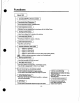
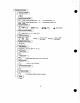
Functions I Indoor Unit Operation OWOFF by Remote controller Sensing the Room Temperature " Room temperature sensor (THERMISTOR) Room temperature control " Maintains the room temperature In accordance with the Setting Temp. Starting Current Control I " indoor fan is delayed for 5 seconds at the starting. Time Delay Safety Control " Restarting is inhibited for approx. 3 minutes.
Remote Controller Operation OWOFF Operation Mode Selection *A O *OO Cooling Operation Mode. (*) --J Salt Dry Operation Mode. L (0) Auto Operation Mode. (ý ) Heating Operation Mode.
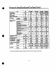
" Product Specifications(Cooling Only) Power Supply Cooling ply MSS-009BIA Unit Kerns e, , z 9,000 940 8.5 nput Running Current ry door(Dry) Lures 9.6 80 BkVhW E.E.R Air Circulation oisture --17, Z,-W-- m mn m in(cfm) TemperatureControl AUTO Wind " e. boCket Hare) as Side Length, std Additional Drain Hose(Inner Dia.) Dimensions Indoor (WxR(D) Outdoor et eg t Indoor Outdoor 9.5/9.5 4-way 4-way Auto Manual Wireless L 64-86°F 2°F ,500 . 909.
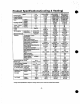
Product Specifications(Cooling & Heating) Power Supply Coding Capacity Heating Capacity Unit o, V, Hz Items Input Running Current COMP. Locked Rotor AMP. E.E.R C.0.13 Air Circulation Btulh Btu/h MSH-012 A 1,115, 60 12,000 12,000 W 1,290 1,900/1,870 2,550/2,500 Heating Collin W A 1,290 11.7 1,900/1,870 8.5/9.0 2,550/2,500 11.5/12.0 Heatin A 11.7 8.519.0 11.5112.0 A A Btu/hW 27 27 9.5/9.5 2.78/2.78 10 ( 350) 49.5 49.5 9.5/9.5 2.9/2.9 13(460 68 68 9.0/9.0 2.6/2.
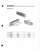
0 Dimensions (1) Indoor Unit [-jzý_, Installation plate I hole cover " Tubing hole cover MODEL DIM 9k, 12k 18k, 24k w mm(inch) 900(35.4") 1,080(42.5") H mm(inch) 290(11.4") 290(11.4') D mm(inch) 183(7.2') 183(7.
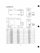
(2) Outdoor Unit valve Gas side 3-way valve (9k, 12k) Gas side 3-way valve 3-wav valve " (18k, 24k) MODEL DIM 9k, 12k 18k, 24k w mm(inch) 801(31.5) 870(34.3) H mm(inch) 555(21.8) 655(25.8) D mm(inch) 262(10.3) 320(12.6) L1 mm(inch) 339(13.3) 370(14.6) L2 mm(inch) 37(1.5) 25(1.0) L3 mm(inch) 543.6(21.4) 630(24.8) L4 mm(inch) 11.4(0.45) 25(1.0) L5 mm(inch) 591(23.3) 546(21.5) L6 mm(inch) 105(4.13) 162(6.4) L7 mm(inch) 105(4.13) 162(6.4) L8 mm(inch) 72.5(2.
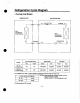
Refrigeration Cycle Diagram " " Cooling Only Models INDOOR UNIT OUTDOOR UNIT t_CAPILIARYTUBE LIQUID SIDE t HEAT EXCHANGER (EVAPORATOR) HEAT EXCHANGER (CONDENSER) COMPRESSOR GAS SIDE i MODEL 9k, 12k (Cooling Only) Pipe size(Diameter:o) Piping length Gas Liquid Rated Max Rated Max 112" 1/4' 7.62m(25ft) 15m(5oft) 5m(16ft) 8m(26ft) 7.
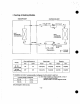
" " Cooling & Heating Models INDOOR UNIT OUTDOOR UNIT CAPILLARYTUBE f- CHECKVALVE HEAT EXCHANGER HEAT EXCHANGER (CONDENSER) (EVAPORATOR) I / \ i f GAS SIDE REVERSING VALVE ----º COMPRESSOR 1 .- COOLING .4 -- HEATING Pipe size(Diametero) MOD E L 9k, 12k (Camay a Heating) 18k, 24k (CodkV a Heating) Piping length Elevation Gas Liquid Rated Max Rated Max 1/2" 1/4" 7.62m(25ft) 15m(50ft) 5m(16ft) 8m(26tt) 5/8" g/8 7.
. Wiring Diagram (1) Indoor Unit 1. MSS-012, MSS-018, MS"18, MSS-024, MSF4424 STEP IROOM) ý / BLOC 1 CN"MOTOR GN-UP/DOWN I- THERMISTOR (PIPE) MAIN P.C.B v z a m U fl j ý a m 3 >ý - - > i -> O Q PILLAR TERMINAL O N a 0 g X INDOOR WIRING DIAGRAM " 3854AR7074A 2. MSS-009, MSS-012 BLDC CN-UPIDOINN ON-MOTOR x r t U MAIN P.C.
(2) Outdoor Unit " Cooling Only Models 1.9k, 12k \V OUTDOOR WIRING DIAGRAM ýlaaczx v w lO.a ý"'ý 2. 18k LJ 3.24k EuEr les msnl 4nl ý 11y A " row+. 1 Eq 3 BL Eq O Bq GfOKOt EA SK BL i 1 ý ý K q 5 L CONK I.
" " Cooling & Heating Models 1.12k 2.18k " 3.
Operation Details 0 (1) The function of main control 1. Time delay Safety Control " 3min.; The compressor operation is delayed for 3 minutes to balance the pressure of cycle. (Protection of compressor) " 5sec.; The indoor fan Is delayed for 5 seconds, when operating initially, to prevent noises occurred by the vertical louver and wind. " 2min.
i 4. Auto Operation (Electronic control mode) -The operation procedure is shown below. (Goofing & Heating Model) I I I Press Start/Stop Button I Select Auto Operation Mode I Check the Room temperature I Operation mode Indoor fan speed are decided automatically by the unit electronic control.
Auto Operation for Soft Dry(only Heating Model) " The Setting temperature will be same that of the auto operation for cooling. - Compressor ON temperature; Setting temperature +2°F - Compressor OFF temperature; Setting temperture -1 °F Intake-air temp. below WF Over 68°F-below 70°F over 86°F Setting terrp.
0 5. Soft Dry Operation Mode " During Soft Dry Operation, the compressor ON temperature is the setting temperature plus 2°F, the compressor OFF temperature is the setting temperature minus 1 °F. " When the room temperature rises over the compressor ON temperature, the operation mode is switched to the Cooling operation. " When the room temperature falls between the compressor ON temperature and OFF temperature, the operation mode is switched to the Soft Dry Operation. *The operation diagram Is shown below.
" 6. Heating Operation Mode(only Heating Model) The unit will operate according to the setting conditions by the remote controller. The operation diagram is shown below. INTAKE AIR TEMP. SETTING TEMP. +60F (Compressor OFF) A SETTING TEMP. (Compressor ON) nwwrºm loses INDOOR FAN SPEED COMPRESSOR g Selecting Low tan speed ON 10 OFF I A r rwmm rrvenn 1 min.
rý u Defrost Control " Defrost operation is controlled by timer and sensing temperature of outdoor pipe. " The first defrost starts only when the outdoor pipe temperature falls below 21°F after 60 minutes passed from starting of heating operation and more than 10 minutes operation of compressor. " Defrost ends after 12 minutes passed from starting of defrost operation or when the outdoor fan operates within 4 minutes after the outdoor pipe temperature rises over WF even if before 12 minutes.
" 7. Cooling or Heating Mode with Sleep Mode Auto Control " When selecting the Cooling( * ) or the Heating() combined with the Sleep Mode Auto Control(*), the operation diagram is as following. Cooling Mode with the Sleep Mode " The setting temperature will be automatically raised by 2°F 30 minutes later and by 4°F 1 hour later. " The operation will be stopped after 1, 2, 3, 4, 5, 6, 7 hours. 30 minutes INTAKE AIR TEMP. 30 minutes 2°F 2F ° SETTING TEMP. +1°F (Compressor ON) SETTING TEMP.
" 8. Forced Operation " If you lose wireless remote controller, you can operate the unit with forced operation button. " The standard conditions are shown below. Heating Model Cooling Model Room Temp ? 76°F 70°F 5 Room Temp < 76°F Room temp < 70°F Operation Mode Cooling Cooling Soft Dry Heating Indoor Fan Speed High High Softe Dry Rule High Setting Temp.
Test Mode 0 Test operation will be set by pushing the "Test key" on the main PWB Assy. Each test operation by pushing count of 'Test key" is as well as the following. (1) Indoor " Once push : Ignore communication error. " Twice push : Shorten the proceeding time.(1 min -+ 1 sec) " 3 Times push : Shorten the proceeding time.(1 hour- 1 sec) " 4 Times push : All LED ON " 5 Times push : Up/Down Step Motor ON. " 6 Times push : Right Step Motor ON. (Not on all Models) " 7 Times push : Left Step Motor ON.
" Display Function Operation Indicator I O " Cooling, Soft Dry, Fan, Heating Sleep timer Indicator " Sleep Mode Timer Indicator I 0 -Timer Mode Defrost Indicator or Hot start Indicator : Cooling & Heating Model only 0 OUT DOOR : only Cooling Model " Hot-start, Defrost " Compressor ON " BUZZER SOUND " " Power Input or Reset : One short beep. : One tong beep. " When Operation Stop Button Is pressed Stop are pressed : Two short beep.
Installation IMPORTANTI Please read this instruction sheet completely before installing the product. This air conditioning system meets strict safety and operating standards. As the installer or service person, it is an important part of your job to install or service the system so it operates safety and efficiently. " Installation or repairs made by unqualified persons can result in hazards to you and others.
" (1) Installation Parts Provided ----- --------- - - - -1. Type "A' screw s.. .r 2. Installation Plate 3. Type '13' screw _ 4 4. Holder Remote-Controller $ a_-p '_ (2) Installation of Indoor, Outdoor unit 1) Selection of the best location 1. Indoor unit. -There should not be any heat source or steam near the unit. " There should not be any obstacles to prevent the air circulation. " A place where air circulation in the room will be good. " A place where drainage can be easily obtained.
0 2) Indoor Unit Installation The mounting wall should be strong and solid enough to protect it from the vibration. 1.Mount the installation plate on the wall with four Type "A' screws. (it mounting the unit on the concrete wall, consider Installation Plate o. .o using anchor bolts.) " Always mount the Installation Plate horizontally by aligning the marking-off line by means of the thread and a level. marking-ott line p/ Type 'A' screw / Thread Weight 2. Drill the piping hole with 70mm(2.
" (3) Piping and Drainage of Indoor Unit 1) PREPARATION OF PIPINGS I i. Cut the pipes and the cable. Ace VAN x " Use the pipes purchased locally. " Measure the distance between the indoor and the outdoor unit 0 Poo started " Cut the pipes a little longer than measured distance. " Cut the cable 1.5m(5.0 ft) longer than the length of the pipe. a 2. Remove burrs. Pipe " Remove burrs from cut edges of pipes. " Turn the pipe end toward down to avoid the metal powder entering the pipe.
2) Connection of Pipings 1. Remove the indoor tubing with Drain hose from the hole " Remove tubing hider and pull the tubing out of the chassis. 2. Replace the tubing holder into original position. " Recommended SPEC. of a additional Drain Hose. Joint Part The materia l of Dra in hose Inner size MAX. ol(imm(SV) Material soft PVC Tubing Soft PVC hose In9beWM dedwihW koMm MaWA " Foamed Polyethylene or equivalent Is recommended.
" 6. Indoor unit installation " Hook the indoor unit onto the upper portion of installation plate. (Engage the two hooks of the rear top of the indoor unit with the upper edge of the installation plate.) Ensure the hooks are properly seated on the installation plate by moving it left and right Connecting cable - t Drain hose 7. Connecting the pipings to the indoor unit " Align the center of the pipings and sufficiently tighten the flare nut with fingers.
:,For the left pipings 3. Route the indoor tubing with the drain hose to the piping hole as desired position. Tubing To remove the holder, press the bottom of chassis near the holder upward and pull the tab f Press out of its hole. 4. Insert the pipings, power supply cord and connecting cable Into the piping hole.
0 5. Insert the connecting cable into the indoor unit " Don't conned the cable to the indoor unit. " Make a small loop with the cable for easy connection later. 6. Tape the tubing, drain hose and the connecting cable. Indoorloutdoor connecting cable Taping as side piping 7. Indoor unit installation " Hook the indoor unit onto the upper portion of installation plate.
10. Set the pipings and the connecting cable to the back of the chassis with the tubing holder " Hook the edge of tubing holder to tap on chassis and push the bottom of tubing holder to be engaged in the bottom of chassis. Drain hose Taping " \ Tubing holder ý(ýFFlook I (2pu5h 11. Indoor unit installation " Hook the indoor unit onto the upper portion of installation plate. (Engage the two hooks of the rear top of the indoor unit with the upper edge of the Connecting installation plate.
" (4) Connecting Pipings and the cable to Outdoor unit 1) Connecting the pipings to the Outdoor unit 1. Align the center of the pipings and sufficiently tighten the flare nut with fingers. 2. Finally, tighten the flare nut with torque wrench until the wrench clicks. " When tightening the flare nut with torque wrench, ensure the direction for tightening follows the arrow on the wrench. Torque Pipe Size Outdoor unit Gas side piping (Bigger Dia.) 1.8kg-m(13ft.
" Connection method of the connecting -cable(Example) (1) Dismount two-caps on the conduit panel. (2) Make a hole appropriate for the passage of connection cable through on cap by tool. (for low voltage line) (3) Pass the connecting cable through the hole. (4) Property connect the cable on the terminal block (5) Fix the connection cable with clamp cord provided on the unit not to have strain at the terminal when the connection cable Is pulled outside up to a 35 pound weight.
" (5) Checking the Drainage and Connecting the cable to Indoor unit 1) Checking the Drainage 1. Remove the Grille from the cabinet. " Set the up-and-down air direction louver to open position (horizontally) by finger pressure. " Remove 3 screws. " To remove the Grille, pull lower the left and right side of the grille toward you (slightly tilted) and lift it straight upward (Four tabs on the top inside edge of chassis are clear of their slots). " Outside drain hose should be lower than inside.
2) Connect the cable to the indoor unit " 1. Connect the wires to the terminals on the control board Individually according to the outdoor unit connection. " Ensure that the color of the wires of outdoor unit and the terminal No. are the same as those of indoor unit respectively. " Be sure to refer to the wiring diagram label inside the cover control and carry out the correct field wiring. Wrong wiring can cause the unit to misoperate to result in a fire hazard.
" 3) Forming the pipings 1. Wrap the connecting portion of indoor unit with the Insulation material and secure It with two Plastic Bands.(for the right pipings) " n you want to connect an additional drain hose, the end of the drain-outlet should keep distance from the ground.(do not dip it into water, and fix it on the wag to avoid swinging In the wind.) Seal a small opening around the pipings with gum type sealer. Main hose ' T ping I a Incase of the Outdoor tmit.
Settfemont of Outdoor Unit " Anchor the outdoor unit with a bolt and nut (e10mm) tightly and horizontally on a concrete or rigid mount. Bolt " When installing on the wall, roof or rooftop, anchor the mounting base securely with a nail or wire assuming the influence of wind and earthquake. " in the case when the vibration of the unit is conveyed to the house, settle the unit with an anti-vibration rubber. i.
v r/v.".a ý.v"" " Name and Function-Remote Controller 1) Cooling Model E[] Operation display Displays the operation conditions. I Remote Controller ® Start/Stop Button " Operation starts when this button is pressed, and stops when the button Is pressed again. Signal transmitter " The fan blows at low speed when start button is pressed initially, after a while the fan speed will be reached at the desired speed. Transmits the signals to the room air conditioner.
2) Heating Model p Operation display Displays the operation conditions. I Remote Controller ® Start/Stop Button " Operation starts when this button is pressed, and stops when the button is pressed again. Signal transmitter " The tan blows at low speed when start button is pressed Transmits the signals to the room air conditioner. initially, after a while the fan speed will be reached at the desired speed. Qs Operation Mode Selection Button Used to select the operation mode.
" (1) 9k, 12k Models(Cooling Only, Cooling & Heating) Hazardous voltage can cause ELECTRIC SHOCK or DEATH. Turn off circuit breaker before you start checking or servicing. 1. To remove the Grille from the Chassis " Set the up-and-down air discharge lower to open position (horizontally) by finger pressure. " Remove the securing screws. " To remove the Grille, pull the lower left and right side of the grille toward you (slightly tilted) and lift it straight upward. 2.
" Remove 2 securing screws. 0 " Unhook the three hooks. " Pull the control box out from the chassis carefully. 3. To remove the Discharge Grille. " Remove the securing screw. " Pull the discharge grille out from the chassis carefully. r-I L-j 4. To remove the Evaporator. " Remove two screws on the left side of the evaporator.
" " Push right carefully in order to unhook the tabs on the right side of the chassis and pug the evaporator toward you. 5. To remove the Cross-Flow Fan " Loosen the screw securing the cross-flow fan to the fan motor(do not remove). " " Pull the left end of the cross-flow fan with the self-aligning bearing out the groove. " Remove the cross-flow fan by sliding it out from the shaft of fan motor. 6. To remove the Fan Motor " Pick g up from the groove. (Do not remove a black rubber as a spacer).
(2) 18k, 24k Models(Cooling Only, Cooling & Heating) I Grille Chassis 0 Hazardous voltage can cause ELECTRIC SHOCK or DEATH. Turn off circuit breaker before you start checking or servicing. 1. To remove the Grille from the Chassis " Set the up-and-down air discharge lower to open position (horizontally) by finger pressure. " Remove the securing screws at the bottom of grille.
0 " Remove three screws fixing control box and motor. " Remove control box assembly holding two hooks fixing upper sides of motor. 3. To remove the Discharge Grille. " Remove a screw on the left side of chassis. " Pull the right side of the discharge grille out from the chassis first and left side carefully. r LJ 4. To remove the Evaporator. -Unhook the tab on the left inside edge of the chassis by pressing it outwards. -47- L.
" Slightily pull the evaporator until left tab on end- plate is clear of the chassis. O~ " Lift the left side of evaporator slightly from the chassis carefully. r " Push right carefully in order to unhook the tabs on the right inside of the chassis and pull the evaporator toward you. 5. To remove the Cross-Flow Fan. " Loosen the screw securing the cross-flow fan to the fan motor shaft(do not remove). " Pull the left end of the cross-flow fan with the selfaligning bearing out the groove.
" Cycle Troubleshooting Guide 1. Trouble analysis 1. Check temperature difference between intake and discharge air and operating current. Temp. difference :approx. 0°F Current All amount of refrigerant leaked :less than 80% of out. rated current Check refrigeration cycle. Temp. Difference Temp. difference :approx. a°C( 140F) I :less than 80% of Current rated current Refrigerant leakage Clog of refrigeration cycle Defective compressor Temp.
LJ 2. Product does not operate at all. (" Refer to Electronic Control Device drawing and Schematic diagram.) Turn off Main Power .Cý_ (After 10 seconds) Tum on Main Power Does "beeping" sound is made from the Indoor Unit? YES NO Primarily, the operating condition of Micom is OK.
i 3. The product Is not operate with the remote controller. Turn on Main Power While the compressor has been stopped, the compressor does not operate owing to the delaying function for 3 minutes after stopped. V When the compressor stopped Indoor Fan is driven by a low speed. At this point the wind speed is not controlled by the remote controller. (When operated in the Sleeping Mode, the wind speed is set to the low speed by force.
0 4. Compressor/Outdoor Fan are unable to drive. Turn on Main Power Operate "Cooling Mode( * )° by setting the desired temperature of the remote controller is less than one of the indoor temperature by 20F at least. When in Fan Mode, Compressor/Outdoor Fan is stopped. V( Check the sensor for indoor temperature is attached as close as to be effected by the temperature of Heat Exchanger(EVA).
U 5. When Indoor Fan does not operate.
U 6. When Vertical Louver does not operate. " Confirm that the Vertical Louver is normally geared with the shaft of Stepping Motor. " ft the regular torque is detected when rotating the Vertical Louver with hands ý Normal " Check the connecting condition of CN-UP/DOWN Connector " Check the soldering condition(on PW B) of CN-UP/DOWN Connector I Check the operating circuit of the Vertical Louver " Confirm that there is DC +12V between pinp(RED) of CN-UP/DOWN and GND.
" 7. When a comunication error occurs. " The operation indicator of Indoor unit blinks five times. " The red indicator of Outdoor unit blinks five times. Check the connecting wires between Indoor and Outdoor unit for the connecting error and the contacting condition. Check the installation condition of outdoor unit. Check for the communication error and the operating condition of product after also operating with the remote controller, then taking above 2 minutes.
0 8. The phenomena in case of connecting error INDOOR UNIT Connector Type CN-DC/DC Phenomena Condition Open and connecting error " The same as the phenomenon of Outdoor Unit. p Blue Q Black (D Brown © Red CN-MOTOR Open Open CN-UP/DOWN Short between terminals CN-DISP Open -The indoor fan does not operate. " The operation indicator of Indoor unit blinks 8 times. " The up/down vane does not operate. " The up/down vane does not smoothly operate. " It does not operate with a remote controller.
" OUTDOOR UNIT Connector Type Phenomena Condition " All functions stop. OPEN " The operation with the remote controller, forced and test one do not operate. CN - POWER Connecting reversely " PWB pattern is damaged when applying the power. OPEN " An functions stop or the compressor does not operate. " The operation with the remote controller, forced and test one do not operate. Connecting reversely " All functions stop. " The operation with the remote controller, forced and test one do not operate.
0 9.
" Electronic Control Device (1) MAIN PWB ASSY(Indoor Unit) SW2 e 00 00 ON-RIGHT 000 EST KEY T CN"iH "' d s GND 0 Oak dl-0IBV IDC72 " ° p 0 Cif R,5 0 aP_.'aRM,. 0 _.it1'" 0 PWB a ýQ D O ASSr:6871AQ2318 ýRw O O CN-0CNC 19 19 O O 0000 a s 9 O 0000 R11 a a--aroR13 M4 a-+ O 812 .
0 (2) MAIN PWB ASSY(Outdoor Unit) 01"POIE11 C °ýý' G p p m 00 a 12\ Cot ,Dc °° iC'lCýeý2w ýq \ý- S e `a' 1 C D a py2 O ý p,!ý o °Q"ý ý ocsý °°° 8 D,-34 o e ýý e-e uel 0 ou o eý o p " ate' ' p (ý ° feo Y 'j a o u ý/yýýRýy C., ice of nom'- 11T-COW .u ° O !j U. O O . ý , 0 o eu O eý,yro ,,c Da aeeo-- b 1 eCTRe" M, pT M3.--- \lý-e Gh® ý-N-. Cro® p Rr-ýwýr p ýCt QIIy r-r O y a ° .
U (3) DISPLAY PWB ASSY < 9k, 12k > LDt ftn O ® O LD2 ® ®6046AQ302OA U R.ASM O LD LD4 (P/No: 6047AQ3021 E) < 18k, 24k > " LD1 LD2 iý 7 CN-MAIN LD3 LD4 P.C.
Schematic Diagram -62- n u
n U -63-
Exploded View & Replacement Parts List 1.
Parts List(9k, 12k) " No. HEAT CONTROLLER PART No. PARTS NAME O'TY gk, 12k MSS-0098 MSS-012B 1 1 1 1 1 1 1 1 PLATE INSTALLATION 2 HOLDER TUBE 2021-0001 ... ..... . 2021-0002 3 MOTOR ASSY 2010-0001 1 1 4 CHASSIS ASSY 1 1 5 6 FAN ASSY CROSS BEARING ASM 2021-0003 .............. 2051-0001 7 EVAPORATOR ASSY 8 9 - THERMISTOR ASSY "PWBASSY, MAIM" 2052-0001 REMARK ('R' means MSH-012B service parts) 1 ....................... .. . .. 1 1 ... ... .. 1 - 1 1 .................
2.
Parts List(18k, 24k) U No. (YTY 18k REMARK ( ' R " means MSS-024B MSH-024B service parts) 24k MSS-018B MSH-018B 1 PLATE INSTALLATION 2021-0001 1 1 1 1 2 HOLDER TUBE 2021-0074 1 1 1 1 3 MOTOR ASSY 2010-0003 1 1 1 1 4 CHASSIS ASSY 2021-0069 1 5 " PARTS NAME HEAT CON TROLL ER PART No. FAN ASSY CROSS . ....... ......
I Outdoor Unit(9k, 12k) n oý Yf 7DDD \ ,\ I MM I Tom, L-----_ r -_--7 M co ( .ý"® m - n cD \ ý i m m m mm J -'------------ ` ,.
Parts List(9K, 12K) No. PARTS NAME OITY 12k MSS-009A MSS-012A 2121-0007 1 1 2021-0008 .......... 2031-0009 1 - . ..... 1 - 2031-0004 - 1 1 1 1 9k , " 1 BASE WELD ASM . 2 3 4 CONDENSER COMPRESSOR ASM O.L.P REMARK ("R' means MSH-012A serviceparts) HEAT CONTROLLER PART No. 2031-0003. ................. 2030-0003 ................. .
No. PARTS NAM E 26 BARRIER .. .. ........................ 27 ............................ TOP COVER ASM ........... Q'TY HEAT CONTROLLER PART No. MSS-009A MSS-012A 2021-0070 1 1 1 2021-0014 1 1 1 2021-0013 1 1 1 1 1 1 9k, 12k 28 REAR PANEL 29 PANEL 2021-0015 .................... 30 31 COVER .-..... ....CONTROL CAP 2021-0016 .. .... ............................ 2040-0045 32 CAPILLARY FINAL ASM 33 HEATER(CRANK-CASE1 REMARK ( 'R' means MSH-012A service parts) is - - 1 1 ..
4.
Parts List( 18k) No. 1 2 PARTS NAME BASE WELD ASM CONDENSER HEAT CONTROLLER PART No. O`Ty 18k MSS-018A MSH-018A 2021-0018 1 - 2031-0002 - 1 2031-0001 1 - COMPRESSOR ASM 2030-0002 1 1 4 GROMMET MOUNTING 2040-0012 3 3 5 GASKET 1 1 6 1 1 7 TERMINAL COVER . . . HEATER(CRANK CASE) 2040-0013 - ---------2019-0008 ......
No. PARTS NAME (TTY HEAT CONTROLLER PART No.
5.
Parts List(24k) " No. 1 2 " PARTS NAME BASE WELD ASM CONDENSER QTY 24k PART No. MSS-024A MSH-024A 2021-0078 1 - 2021-0079 ............... 2031-0002 - 1 - 1 1 .....................
Q'TY 24k No. PARTS NAME PART No. MSS-024A 26 "CAPILLARY, BENT" REMARK (' R' means MSH-024A 2035-0004 1 - 2035-0006 - 1 27 PANEL 2021-0015 1 1 28 COVER CONTROL 2021-0020 1 1 2040-0045 -----2010-0004 --------2021-0021 1 2 1 1 1 1 29 CAP ..-......... ................. ..
Indoor Parts List(9k, 12k) ICJ PARTS NAME No. PLATE INSTALLATION 1 9O2 k MSS-009B MSS-012B 2021-0001 1 1 1 1 1 2 HOLDER TUBE 2021-0002 1 3 MOTOR ASSY 2010-0001 1 1 4 2021-0003 - ---2051-0001 1 5 CHASSIS ASSY ...- -- -- FAN ASSY CROSS 6 BEARING ASM 2052-0001 1 1 1 7 EVAPORATOR ASSY 2032-0002 - - 1 1 - 8 9 1 .......
Indoor Parts List(1 Sk, 24k) No. PARTS NAME PLATE INSTALLATION . 1 . ............ 2 HOLDER TUBE HEAT CONTROUER PART No. MSS-0188 MSH-018B 2021-0001 1 1 1 2021-0074 1 1 1 REMARK ( " R" means MSS-024B MSH-024B service parts) 24k TY 18k - 1 3 MOTOR ASSY 2010-0003 1 1 1 1 ....... ....................
Outdoor Parts List(9k, 12k) PARTS NAME No. " 1 BASE WEKD ASM HEAT CONTROU-ER PART No. 1 k gQ 2 MSS-009A MSS-012A 1 1 2121-0007 1 2021-0008 2 3 CONDENSER COMPRESSOR ASM 2031-0009 1 2031-0004 - 2031-0003 - 2030.0003 2030-0009 4 " O.LP REMARK ( 'R' means MSH-012A service parts) 1 . ................. 1 1 1 -- . 2019-0012 2019-0023 - 1 1 - 1 ------ -- ------ -- -- 1 ....... . .................... ............
No. PARTS NAME HEAT CONTROLLER gQ 2k PART W. 26 BARRIER REMARK ( 'R' means MSH-012A senriceparts) MSS-009A 1 MSS-012A 1 1 1 1 2021-0070 27 TOP COVER ASM 2021-0014 1 1 28 - REAR PANEL 2021-0013 1 1 1_ 29 PANEL 2021-0015 1 1 1 2021-0016 1 1 1 ...2 1 2 2 30... ............. COVER . CONTROL 31.. . CAP 32 CAPILLARY 2040-0045.. 2035-0012 FINAL ASM 2035-0002 1-.
Outdoor Parts List(18k) J No. 1 PARTS NAME BASE WELD ASM aT HEAT CONTROLLER PART No. MSS-018A 2021-0019 " 1 1............. 2031-0002 2031-0001 1 1 1 3 3 COMPRESSOR ASM 4 GROMMET MOUNTING 2030-0002 .......... 2040-0012 5 GASKET 2040-0013 1 ......
No. PARTS NAME HEAT CONTROLLER 1 T PART No. MSS-018A MSH-018A 27 FAN MOTOR 2010-0004 1 1 28 MOUNT MOTOR 2021-0021 1 1 29 EXTRA FAN 2050-0001 1 1 30 31 BARRIER ASM 2021-0075 1 1 2021-0076 1 1 32 "COVER, TOP" 2021-0077 1 1 33 PANEL, REAR' 2021-0024 1 1 PANEL FRONT ASM REMARK (" R" means service pa ns) ........... ...
Outdoor Parts List(24k) r-1 LJ No. 1 PARTS NAME BASE WELD ASM CITY SAT CONTROU.B PART No. MSS-024A 2021-0078 1 2031-0002 - 1 2031-0001 1 - 2030-0001 ........ ... 2035-0014 1 4 COMPRESSOR ASM - -- -------- --MUFFLER ASSY 5 GROMMET MOUNTING 2040-0014 4 4 6 GASKET TERMINAL 2040-0015 1 1 7 TERMINAL COVER 2019-0010 1 1 8 RETAINER TERMINAL 2019-0027 1 1 9 SUMP HEATER 2019-0011 10 2033-0004 1 11 'SERVICE VALVE(3/8")' ................. ...
PARTS NAME No. 26 "CAPILLARY, BENT" UTY 24k HEAT CONTROLLER PART No. MSS-024A 2035-0004 1 MSH-024A 1 2035-0006 27 PANEL 2021-0015 1 1 28 COVER CONTROL 1 29 CAP 2021-0020 2040-0045 1 ---- -- - -2 30 2010-0004 -- -- - 2021-0021 1 1 31 FAN MOTOR ...................
U U Specifications and performance data subject to change without notice. 0 HEAT CONTROLLER, INC.
0 0