HEAT CONTROLLER INSTALLATION INSTRUCTIONS PACKAGE GAS ELECTRIC FEATURING EARTH-FRIENDLY R-410A REFRIGERANT TGC***A-13 SEER (3-5 TONS) SERIES efrigerant 92-21916-38-00
I.TABLE OF CONTENTS I. II. III. IV. V. VI. VII. VIII. IX. X. XI. XII. XIII. 2 Table of Contents ..................................................................................................2 Introduction ............................................................................................................3 Checking Product Received ..................................................................................3 Specifications.............................................................
! Recognize this symbol as an indication of Important Safety Information! ! WARNING THE MANUFACTURER’S WARRANTY DOES NOT COVER ANY DAMAGE OR DEFECT TO THE AIR CONDITIONER CAUSED BY THE ATTACHMENT OR USE OF ANY COMPONENTS, ACCESSORIES OR DEVICES (OTHER THAN THOSE AUTHORIZED BY THE MANUFACTURER) INTO, ONTO OR IN CONJUNCTION WITH THE AIR CONDITIONER.
lines, or be allowed to accumulate in storage tanks. Leak checking should never be done with a mixture of R-410A and air. Leak checking can be performed safely with nitrogen or a mixture of R-410A and nitrogen. 2. Quick Reference Guide For R-410A • R-410A refrigerant operates at approximately 60% higher pressure (1.6 times) than R22. Ensure that servicing equipment is designed to operate with R-410A. • R-410A refrigerant cylinders are pink. • R-410A, as with other HFC’s is only compatible with POE oils.
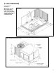
VI. UNIT DIMENSIONS FOR CLEARANCES SEE FIGURE 7. IMPORTANT: THIS UNIT MUST BE MOUNTED LEVEL IN BOTH DIRECTIONS TO ALLOW WATER TO DRAIN FROM THE CONDENSER SECTION AND CONDENSATE PAN.
FIGURE 3 CABINET DIMENSIONS AND ACCESS LOCATIONS I282 FIGURE 4 SUPPLY AND RETURN DIMENSIONS I288 6
! WARNING NEVER TEST FOR GAS LEAKS WITH AN OPEN FLAME. USE A COMMERCIALLY AVAILABLE SOAP SOLUTION MADE SPECIFICALLY FOR THE DETECTION OF LEAKS TO CHECK ALL CONNECTIONS, AS SPECIFIED IN GAS SUPPLY AND PIPING SECTION OF THESE INSTRUCTIONS. VII. INSTALLATION A. GENERAL Install this unit in accordance with The American National Standard Z223.1-latest edition booklet entitled “National Fuel Gas Code,” and the requirements or codes of the local utility or other authority having jurisdiction.
! WARNING FIGURE 5 OUTSIDE SLAB INSTALLATION. CLOSET DISTRIBUTION SYSTEM. SLAB FLOOR CONSTRUCTION. THIS UNIT MAY BE USED TO HEAT THE BUILDING OR STRUCTURE DURING CONSTRUCTION IF THE FOLLOWING INSTALLATION REQUIREMENTS ARE MET.
C. ATTACHING EXHAUST AND COMBUSTION AIR INLET HOODS IMPORTANT: Do not operate this unit without the exhaust/combustion air inlet hood properly installed. This hood is shipped in a carton in the blower compartment inside the unit and must be attached when the unit is installed. See Figure 3. To attach exhaust/combustion air inlet hood: 1. Remove screws securing blower access panel and remove access panel. For location of blower access panel, see Figure 2. 2.
FIGURE 7 CLEARANCES I297 F. ROOFTOP INSTALLATION 1. Before locating the unit on the roof, make sure that the roof structure is adequate to support the weight involved. (See Electrical & Physical Tables in this manual.) THIS IS VERY IMPORTANT AND THE INSTALLER’S RESPONSIBILITY. 2. For rigging and roofcurb details, see Figures 8, 9, 10 and 11. 3. The location of the unit on the roof should be such as to provide proper access for inspection and servicing. 4.
FIGURE 8 FLAT ROOFTOP INSTALLATION, ATTIC OR DROP CEILING DISTRIBUTING SYSTEM. MOUNTED ON ROOFCURB. CURB MUST BE LEVEL. I299 Place the unit as close to the conditioned space as possible allowing clearances as indicated. Run ducts as directly as possible to supply and return outlets. Use of non-flammable weatherproof flexible connectors on both supply and return connections at unit to reduce noise transmission is recommended.
FIGURE 9 B LIFTING DETAIL SPREADER BAR LIFTING BEAM CABLE OR CHAIN A C.G. 38 D .25 25 .7 5 5/8 SHACKLE (EACH CORNER) CORNER WEIGHTS BY PERCENTAGE A B C D 22% 27% 23% 28% C FIGURE 10 I296 FIGURE 11 UNIT ROOFCURB ROOFCURB HOLD DOWN BRACKET TYP. (4) PLCS. ROOFTOP UNIT ROOFTOP UNI GASKET GASKET NAILER STRIP NAILER STRIP DUCT* DUCT* GASKET (FULL PERIMETER AND ON DIVIDERS, MUST BE ABOVE DUCT AND INSULATION PANEL FLANGES.
VIII. GAS SUPPLY, CONDENSATE DRAIN AND VIII. PIPING A. GAS CONNECTION IMPORTANT: Connect this unit only to gas supplied by a commercial utility. 1. Install gas piping in accordance with local codes and regulations of the local utility company. In the absence of local codes, the installation must conform to the specifications of the National Fuel Gas Code, ANSI Z223.1 - latest edition. NOTE: The use of flexible gas connectors is not permitted.
In making gas connections, avoid strains as they may cause noise and damage the controls. A backup wrench is required to be used on the valve to avoid damage. The capacities of gas pipe of different diameters and lengths in cu. ft. per hr. with pressure drop of 0.3 in. and specific gravity of 0.60 (natural gas) are shown in Table 1. After determining the pipe length, select the pipe size which will provide the minimum cubic feet per hour required for the gas input rating of the furnace.
FIGURE 15 FIGURE 14 MANIFOLD PIPE D. ADJUSTING OR CHECKING FURNACE INPUT – Natural Gas Line Pressure 5 - 10.5 W.C. – LP Gas Line Pressure 11 - 13 W.C. – Natural Gas Manifold Pressure 3.5 W.C – LP Gas Manifold Pressure - 10 W.C. Supply and manifold pressure taps are located on the gas valve body 1/8 N.P.T. and on the manifold. Use a properly calibrated manometer gauge for accurate gas pressure readings. Only small variations in the gas flow should be made by means of the pressure regulator adjustment.
TABLE 3 METER TIME IN MINUTES AND SECONDS FOR NORMAL INPUT RATING OF FURNACES EQUIPPED FOR NATURAL OR LP GAS INPUT BTU/HR 40,000 60,000 80,000 100,000 FIGURE 16 CONDENSATE DRAIN METER HEATING VALUE OF GAS BTU PER CU. FT. SIZE 900 1000 1040 1100 2500 CU. FT. MIN. SEC. MIN. SEC. MIN. SEC. MIN. SEC. MIN. SEC.
FIGURE 17 RECOMMENDED BRANCH CIRCUIT DISCONNECT LOCATION TABLE 4 BRANCH CIRCUIT COPPER WIRE SIZE (Based on 1% Voltage Drop)* 200 150 100 50 6 8 10 14 15 4 6 8 12 20 4 6 8 10 25 4 4 6 10 30 3 4 6 8 35 3 4 6 8 40 2 2 3 3 4 4 6 6 45 50 BRANCH CIRCUIT AMPACITY SUPPLY WIRE LENGTH-FEET *Taken from National Electric Code BRANCH CIRCUIT DISCONNECT TO POWER TO THERMOSTAT I317A NOTES: 1. Wire size based on 60°C rated wire insulation and 30°C Ambient Temp. (86°F). 2.
FIGURE 18 FIGURE 19 TYPICAL THERMOSTAT WIRING I658 WIRE SIZE, AWG CONDUIT SIZE HOLE SIZE NOTES: 14 1/2 7/8 12 1/2 7/8 10 1/2 7/8 8 3/4 1-31/32 6 1 1-23/64 4 1 1-23/64 3 1-1/4 1-23/32 2 1-1/4 1-23/32 1 1-1/2 1-31/32 0 1-1/2 1-31/32 00 2 2-15/32 000 2 2-15/32 1. DETERMINE REQUIRED WIRE SIZE FROM MINIMUM CIRCUIT AMPACITY SHOWN IN INSTALLATION & OPERATING INSTRUCTION. 2. BOTTOM POWER ENTRY WILL NOT ACCOMMODATE WIRE LARGER THAN #2 AWG (SHADED AREA). B.
TABLE 6 Thermostat Load Amps FIELD WIRE SIZE FOR 24 VOLT THERMOSTAT CIRCUITS 3.0 2.5 2.0 16 16 18 50 SOLID COPPER WIRE - AWG. 14 12 10 10 14 12 12 12 16 14 12 12 100 150 200 250 Length of Run – Feet (1) 10 10 10 300 (1) The total wire length is the distance from the furnace to the thermostat and back to the furnace. NOTE: DO NOT USE CONTROL WIRING SMALLER THAN NO. 18 AWG. rays, lamps, televisions, radios or air streams from registers.
If the control detects the following failures, the LED will flash on for approximately 1/4 second, then off for 3/4 second for designated failure detections. 1 Flash: Failed to detect flame within the three tries for ignition. 2 Flash: Pressure switch or induced draft blower problem detected. 3 Flash: High limit or auxiliary limit open. 4 Flash: Flame sensed and gas valve not energized or flame sensed with no “W” signal. 5 Flash: Overtemperature switch open.
! WARNING SHOULD OVERHEATING OCCUR OR THE GAS SUPPLY FAIL TO SHUT OFF, SHUT OFF THE MANUAL GAS VALVE TO THE APPLIANCE BEFORE SHUTTING OFF THE ELECTRICAL SUPPLY. FAILURE TO DO SO CAN RESULT IN AN EXPLOSION OR FIRE CAUSING PROPERTY DAMAGE, SEVERE PERSONAL INJURY OR DEATH! BURNERS Burners for these units have been designed so that field adjustment is not required. Burners are tray-mounted and accessible for easy cleaning when required.
7. IMPORTANT: Replace all blower doors and compartment cover after servicing the unit. Do not operate the unit without all panels and doors securely in place. 8. Do not allow snow or other debris to accumulate in the vicinity of the appliance.
! WARNING DISCONNECT MAIN ELECTRICAL POWER TO THE UNIT BEFORE ATTEMPTING MAINTENANCE. FAILURE TO DO SO MAY RESULT IN ELECTRICAL SHOCK OR SEVERE PERSONAL INJURY OR DEATH. LUBRICATION IMPORTANT: DO NOT attempt to lubricate the bearings on the blower motor or the induced draft blower motor. Addition of lubricants can reduce the motor life and void the warranty. The blower motor and induced draft blower motor are prelubricated by the manufacturer and do not require further attention.
4. If the coil is coated with oil or grease, clean it with a mild detergent-and-water solution. Rinse the coil thoroughly with water. IMPORTANT: Do not use excessive water pressure. Excessive water pressure can bend the fins and tubing of the coil and lead to inadequate unit performance. Be careful not to splash water excessively into unit. 5. The venturi should also be inspected for items of obstruction such as collections of grass, dirt or spider webs. Remove any that are present. 6.
SPEED TAP BLOCK FIGURE 22 FIGURE 20 INTEGRATED FURNACE CONTROL FIGURE 21 25
FIGURE 22 (Continued) 26
XII. GENERAL DATA - TGC MODELS NOMINAL SIZES 3-5 TONS [10.6-17.6 kW] Model TGC-Series 036A3K-080 036A-3K-120 036A-1K-080 Cooling Performance1 Gross Cooling Capacity Btu [kW] EER/SEER2 Nominal CFM/ARI Rated CFM [L/s] ARI Net Cooling Capacity Btu [kW] Net Sensible Capacity Btu [kW] Net Latent Capacity Btu [kW] Net System Power kW 36,800 [10.78] 11.4/13 1200/1200 [566/566] 35,400 [10.37] 26,200 [7.68] 9,200 [2.7] 3.1 36,800 [10.78] 11.4/13 1200/1200 [566/566] 35,400 [10.37] 26,200 [7.68] 9,200 [2.7] 3.
GENERAL DATA - TGC MODELS NOMINAL SIZES 3-5 TONS [10.6-17.6 kW] Model TGC-Series 042A-3K-080 042A-3K-120 042A-1K-080 Cooling Performance1 Gross Cooling Capacity Btu [kW] EER/SEER2 Nominal CFM/ARI Rated CFM [L/s] ARI Net Cooling Capacity Btu [kW] Net Sensible Capacity Btu [kW] Net Latent Capacity Btu [kW] Net System Power kW 42,500 [12.45] 11.2/13 1400/1450 [661/684] 40,500 [11.87] 30,600 [8.97] 9,900 [2.9] 3.62 42,500 [12.45] 11.2/13 1400/1450 [661/684] 40,500 [11.87] 30,600 [8.97] 9,900 [2.9] 3.
GENERAL DATA - TGC MODELS NOMINAL SIZES 3-5 TONS [10.6-17.6 kW] Model TGC-Series 048A-3K-080 048A-3K-100 048A-3K-135 Cooling Performance1 Gross Cooling Capacity Btu [kW] EER/SEER2 Nominal CFM/ARI Rated CFM [L/s] ARI Net Cooling Capacity Btu [kW] Net Sensible Capacity Btu [kW] Net Latent Capacity Btu [kW] Net System Power kW 50,000 [14.65] 11.45/13 1600/1600 [755/755] 48,000 [14.06] 35,600 [10.43] 12,400 [3.63] 4.19 50,000 [14.65] 11.45/13 1600/1600 [755/755] 48,000 [14.06] 35,600 [10.43] 12,400 [3.
GENERAL DATA - TGC MODELS NOMINAL SIZES 3-5 TONS [10.6-17.6 kW] Model TGC-Series 048A-1K-100 048A-1K-135 060A-3K-100 Cooling Performance1 Gross Cooling Capacity Btu [kW] EER/SEER2 Nominal CFM/ARI Rated CFM [L/s] ARI Net Cooling Capacity Btu [kW] Net Sensible Capacity Btu [kW] Net Latent Capacity Btu [kW] Net System Power kW 50,000 [14.65] 11.45/13 1600/1600 [755/755] 48,000 [14.06] 35,600 [10.43] 12,400 [3.63] 4.19 50,000 [14.65] 11.45/13 1600/1600 [755/755] 48,000 [14.06] 35,600 [10.43] 12,400 [3.
GENERAL DATA - TGC MODELS NOMINAL SIZES 3-5 TONS [10.6-17.6 kW] Model TGC-Series 060A-1K-100 060A-1K-135 Cooling Performance1 Gross Cooling Capacity Btu [kW] EER/SEER2 Nominal CFM/ARI Rated CFM [L/s] ARI Net Cooling Capacity Btu [kW] Net Sensible Capacity Btu [kW] Net Latent Capacity Btu [kW] Net System Power kW 61,000 [17.87] 11.1/13 2000/1900 [944/897] 59,000 [17.29] 42,000 [12.31] 17,000 [4.98] 5.32 61,000 [17.87] 11.1/13 2000/1900 [944/897] 59,000 [17.29] 42,000 [12.31] 17,000 [4.98] 5.
XIII.
Low Med Med Med TGC036A TGC036A TGC036A Cool High Low High 135,000 [39.56] 100,000 [29.31] 100,000 [29.31] 135,000 [39.56] Low Med 80,000 [23.45] Med Low 120,000 [35.17] 80,000 [23.45] Med 80,000 [23.45] Heating Input BTU/hr [kW] 120,000 [35.
Low Med Med Med TGC042A TGC048A TGC060A Cool High Low High Med Low Med Low Med Low Heat Motor Speed From Factory TGC036A Unit Model 135,000 [39.56] 100,000 [29.31] 80,000 [23.45] 100,000 [29.31] 135,000 [39.56] 80,000 [23.45] 120,000 [35.17] 120,000 [35.17] 80,000 [23.
Low Med High TGC042A TGC048A Cool High Med Low Heat Motor Speed From Factory TGC036A Unit Model 80,000 [23.45] 135,000 [39.56] 80,000 [23.45] 120,000 [35.17] Heating Input BTU/hr [kW] 80,000 [23.45] 120,000 [35.
0.1 0.2 — — 605 620 640 680 1100 1200 1300 1400 1500 340 305 275 250 — — — — 225 255 270 300 340 370 — 615 630 655 675 710 745 920 855 800 750 705 1 2 3 4 5 3.6 - 4.4 PITCH DIAMETER 6 .055 .05 DOWNFLOW ECONOMIZER R. A. DAMPER .06 .060 .07 .066 .060 1400 1600 1800 2000 2200 STANDARD INDOOR AIRFLOW - CFM .08 .072 .09 .080 .085 .10 .086 .100 .11 .093 .110 NOTES: 1. PERFORMANCE SHOWN WITH DRY COIL & STANDARD 1 FILTERS 2. STANDARD CFM @ .
0.1 0.2 — — — — — 725 740 770 1200 1300 1400 1500 1600 1700 1800 500 460 410 — — — — — — — — — — 375 410 445 495 535 — — — — 725 740 765 795 825 875 850 820 795 765 745 725 — — “L” 570 520 470 440 395 360 335 — — RPM WATTS 0.3 958 945 905 865 820 4 2 3 4 5 .055 .05 DOWNFLOW ECONOMIZER R. A. DAMPER .06 .060 .07 .066 .060 1400 1600 1800 2000 2200 STANDARD INDOOR AIRFLOW - CFM .08 .072 .09 .080 .065 .10 .086 .100 .
CAPACITY: 4 TON - 13 SEER 0.2 — — — — — 775 800 830 1400 1500 1600 1700 1800 1900 2000 595 525 470 — — — — — — — — — — 425 470 515 560 640 — — — — 775 795 820 855 885 940 910 875 850 815 790 770 — — “L” 670 610 555 505 455 425 385 — — RPM WATTS 0.3 1060 1000 955 910 865 4 .055 .05 ECONOMIZER R. A. DAMPER .06 .060 .040 1200 .07 .066 .060 1400 6 1 2 1800 2000 2200 .08 .072 .070 .09 .080 .085 .10 .086 .100 .
0.2 — — — 780 800 830 860 895 940 970 1015 1500 1600 1700 1800 1900 2000 2100 2200 2300 2400 2500 910 825 755 680 615 550 485 455 — — — — — 390 450 470 530 605 655 735 795 880 935 — 780 795 815 850 880 915 945 975 1015 1040 “L” — — 1095 1040 1015 995 955 930 895 870 840 805 795 780 1040 925 830 780 705 655 590 540 490 425 405 370 RPM WATTS 0.
FIGURE 23 WIRING DIAGRAM 40
FIGURE 24 WIRING DIAGRAM 41
FIGURE 25 WIRING DIAGRAM 42
FIGURE 26 WIRING DIAGRAM 43
FIGURE 27 WIRING DIAGRAM 44
FIGURE 28 WIRING DIAGRAM 45
FIGURE 29 WIRING DIAGRAM 46
FIGURE 30 SYSTEM CHARGE CHARTS 3 TON COOLING - 13 SEER 525 500 115 475 450 425 105 400 95 375 350 85 325 300 75 275 65 250 225 55 200 175 120 125 130 135 140 145 150 155 160 165 170 92-102259-01-01 47
FIGURE 31 SYSTEM CHARGE CHARTS 3.
FIGURE 32 SYSTEM CHARGE CHARTS 4 TON COOLING - 13 SEER 49
FIGURE 33 SYSTEM CHARGE CHARTS 5 TON COOLING - 14 SEER SYSTEM CHARGE CHART - REFRIGERANT 410A 5 TON, 14 SEER 525 500 115 475 450 425 105 400 375 95 350 85 325 300 75 275 250 65 225 55 200 175 120 125 130 135 140 145 150 155 160 165 170 92-102259-05-00 50
COOLING TROUBLE SHOOTING CHART ! WARNING DISCONNECT ALL POWER TO UNIT BEFORE SERVICING. CONTACTOR MAY BREAK ONLY ONE SIDE. FAILURE TO SHUT OFF POWER CAN CAUSE ELECTRICAL SHOCK RESULTING IN PERSONAL INJURY OR DEATH.
FURNACE TROUBLESHOOTING GUIDE (COMBINATION HEATING AND COOLING UNITS WITH DIRECT SPARK IGNITION) ! WARNING HAZARDOUS VOLTAGE DISCONNECT POWER BEFORE LINE VOLTAGE CON- SERVICING. NECTIONS SERVICE MUST BE BY A TRAINED, QUALIFIED SERVICE TECHNICIAN.
NOTE: IF THE SYSTEM GOES INTO LOCKOUT, WAIT 30 SECONDS AND RESET THE SYSTEM.
CM 0109